Results 1 to 9 of 9

Thread: TB-4 Wiring help

Hybrid View

Previous Post Previous Post   Next Post Next Post
  1. #1
    Member
    Join Date
    Jan 2024
    Location
    Netherlands
    Posts
    3
    Quote Originally Posted by Simon Barden View Post
    One capacitor is correct for the wiring diagram.

    I agree that the kit should have two A500k for volume and one B500k pot for tone. It may be worth checking with a multimeter what the mid turn resistance is on the B pot between the middle tag and one of the end ones. If it is linear, then you should be reading around 250k, if log/audio, either nearer 90k or 410k (depending on the end tag chosen). If B is linear, then email Pit Bull and ask them to send out another A pot. If log, then the A and B designations on the kit pots are simply swapped (annoying but it could happen), so use the Bs for volume and the A for tone.

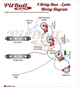
    The pickups supplied have 4-conductor wiring, not the 1+ screen shown in the wiring diagram. Unless you feel like wiring the pickup coils in parallel rather than series for a brighter tone, or adding a coil split switch for single coil sounds, you use:
    Black - signal hot
    Green+screen - signal ground
    Red+White - wires that connect the two pickup coils together internally. Leave unconnected and tape up the bare ends to avoid them shorting out. If you want a coil split, then this red/white combo is connected to an extra 2-way switch that can connect the wires to ground.
    So if I follow you correctly:
    - use the black wire from the neck pickup instead as the blue in the diagram
    -green+screen from neck pickup is signal ground on the first potentiometer
    -use black wire from the bridge pickup instead of the red on the diagram
    -green+screen from bridge pickup as signal ground for second potentiometer
    -tape up red/white wires
    -Use rest of diagram

    But how to make ground with the bridge? there is no internal hole to get there?
    Click image for larger version. 

Name:	Schermafbeelding 2024-01-19 135232.png 
Views:	2267 
Size:	187.1 KB 
ID:	45049

  2. #2
    Moderator Trevor Davies's Avatar
    Join Date
    May 2020
    Location
    Perth
    Posts
    1,742
    Quote Originally Posted by Ivo Kalis View Post
    So if I follow you correctly:
    - use the black wire from the neck pickup instead as the blue in the diagram
    -green+screen from neck pickup is signal ground on the first potentiometer
    -use black wire from the bridge pickup instead of the red on the diagram
    -green+screen from bridge pickup as signal ground for second potentiometer
    -tape up red/white wires
    -Use rest of diagram

    But how to make ground with the bridge? there is no internal hole to get there?
    Click image for larger version. 

Name:	Schermafbeelding 2024-01-19 135232.png 
Views:	2267 
Size:	187.1 KB 
ID:	45049
    Hi Ivo.

    Yes, for the wiring. Just to be sure - each red/white wire is taped up separately.

    For the ground to the bridge - My kit had a small hole drilled from the bridge post hole closest to the control cavity. In the cavity, this hole was very close to the jack socket hole. Hopefully your kit has this predrilled, but if not, it should not to too hard to drill.
    PitBull Builds: FVB-4, LP-1SS, FBM-1, AG-2, TB-4, SSCM-1, TLA-1,TL-1TB, STA-1HT, DSCM-1 Truckster, ST-1, STA-1, MBM-1, MBM custom, GHR-1 (Resonator), FH-5V (Acoustic).

    Scratch Builds: Pine Explorer, Axe Bass, Mr Scary, Scratchy Tele's.

    The little voices in my head keep telling me "build more guitars"

  3. #3
    Member
    Join Date
    Jan 2024
    Location
    Netherlands
    Posts
    3
    Click image for larger version. 

Name:	Naamloos-1.jpg 
Views:	2202 
Size:	658.6 KB 
ID:	45083

    so this is what i thought you described to me. But somehow I only get Static noise from the moment I put in my jack plug.


    What am I doing wrong?

Posting Permissions

  • You may not post new threads
  • You may not post replies
  • You may not post attachments
  • You may not edit your posts
  •