It's been sunny and warm enough to work out side for the past three days, so I've been doing a lot of initial work on the kit.
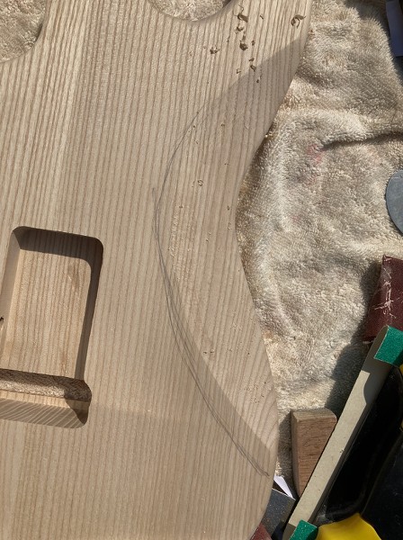
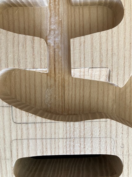
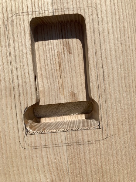
Both the forearm cut and the belly cut are smaller than on a real Strat, so they've both been enlarged to match the general size and shape of my Dave Gilmour Strat. I know that these exact dimensions will have varied over the years, and even from guitar to guitar in the first decades of production because of the hand sanding, but you need to pick some reference point. The belly cut was fairly close and mainly needed lengthening, but it also got slightly deepened. Before:
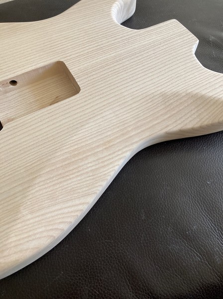
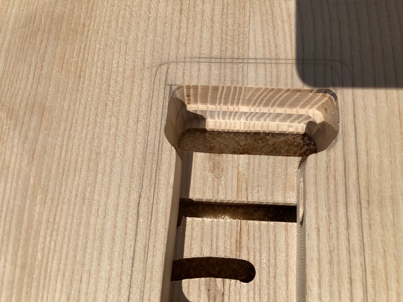
After:
The forearm cut was fairly minimal and much too short, running down to just 1/4 of the body height, so it now extends down to 1/2 way and is gently 'rolled over', rather than being very angular and meeting the top with a very defined line.
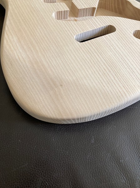
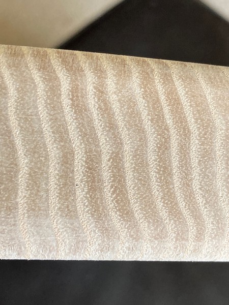
There's been a lot of sanding to do. The factory obviously use a fixed drum sander, rather than an oscillating one, which has left very definite parallel score lines all around the body edge.
It's taken the best part of two days to get rid of these. Didn't have anything coarser than 80 grit paper, but could have done with some P60. I could do a lot of the convex curves with a random orbital sander, but all the concave ones and within the horns was all manual sanding. At least there's nothing to show up under the lacquer now.
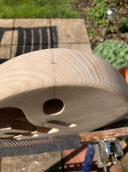
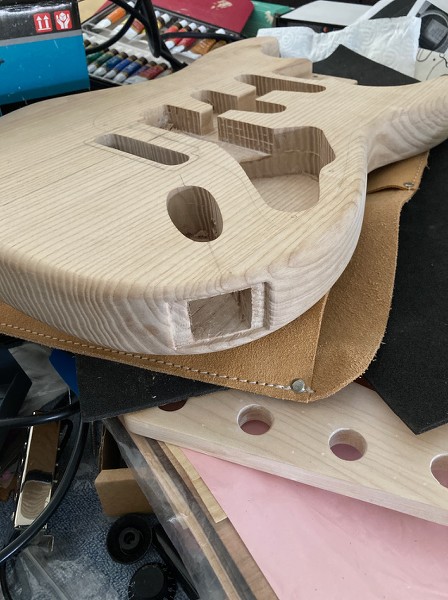
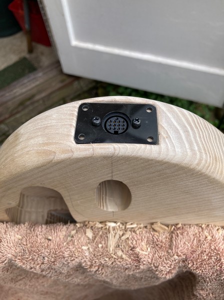
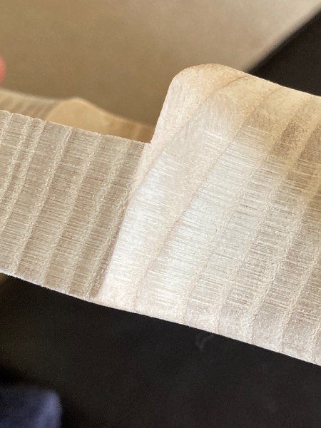
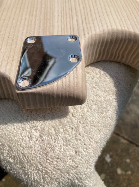
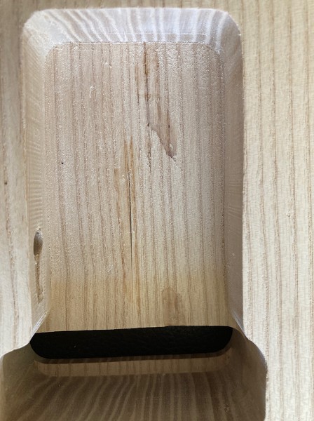
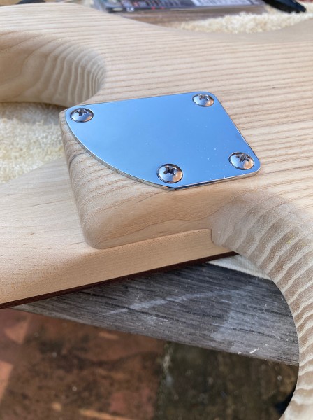
The rounded heel plate arrived yesterday, so I rounded over the lower heel edge in what (I think) is a similar manner
to the latest Fender USA contemporary style.
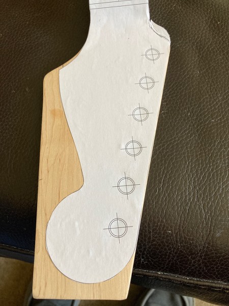
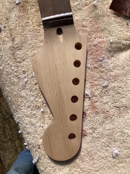
The headstock was cut to give a certain classic look. Paper template first stuck on:
The kit necks have a rather elongated section between the nut and the 'flared out' section of the headstock, so the tuners will always be further away from the nut than on their inspiration.
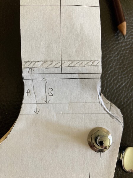
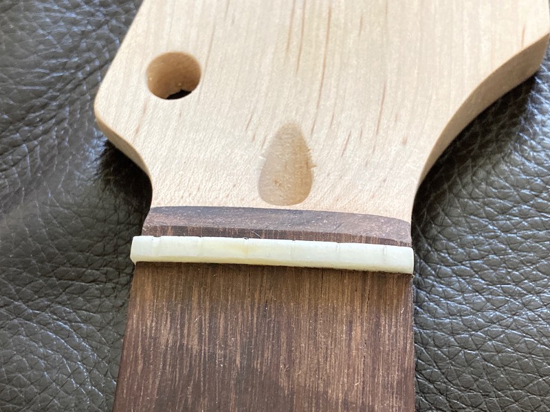
Here's a close-up of the nut area of the headstock. I've shaded in where the kit nut is, and you can see where the template thinks the nut should be. Because the bass side curves of the template and actual headstock are different' it's not easy to say exactly how much the neck is stretched in this area, but I drew lines to roughly the same relative points on the curves, and measured from the respective nut positions, and A (kit) is 27mm, B (vintage) is 14mm. So a 13mm stretch.
Obviously the positioning of the template is dictated by the main headstock outline. The headstock holes are slightly further apart than on a vintage headstock, so fitting vintage tuners (that need to butt up against one another as they share a common mounting screw) isn't an option here, at least not without plugging the holes and redrilling. So I positioned the template so that the high E tuner hole corresponded with the high E template hole in order to keep the scroll end of the headstock as near the nut as possible. The headstock is already stretched out compared to the original, so there was no point using the low E tuner as the reference point and moving the scroll end another 3mm or so away from the nut.
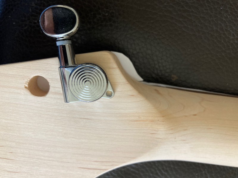
Luckily I wasn't planning to fit vintage-style tuners, so I fitted a tuner (NorthWest Guitars locking style) to make sure there was sufficient gap between the tuner and the end of the headstock, but this was fine.
On my EX-1 kit, the low E tuner sits right against the edge of the headstock.
Edit: Forgot to add the rough cut-out headstock picture. I did a bit more more sanding after this, especially on the nut/fingerboard join area to get that looking straighter. It was all a bit wonky straight from the factory, which spoils the look:
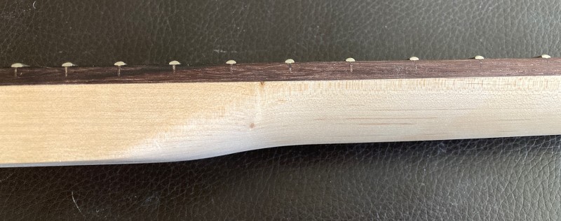
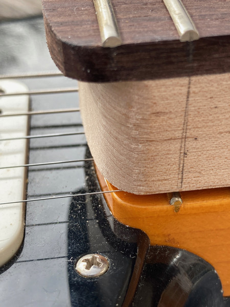
I also smoothed off the neck's heel so that it flowed into the heel join area, without the large flat area that normally pokes out a couple of cm on this style of neck.
When the neck is put on the guitar, the combination of the two lots of heel roundings gives a much more natural heel to moving your hand up the dusty end, with no impediment to upper fret access.
I removed the nut to replace it with a bone one, but all my pre-shaped nuts were too low, as the nut slot on the guitar is quite deep. The old nut wasn't glued-in very well, there was a gap between it and the bottom of the sot on the bass side, and it only took one light tap to free it. So I cut a nut from an acoustic saddle blank I had, using the old one as a template. No point in finessing the shape now, as that will get done in the final set up,
I've had to fix cracks and small faults in the body, which I'm not happy about. Some were tear outs from drilling (dull bits) and router tear-outs (routed edges seem clean so the router bits seem to have been pretty sharp). But also what now seems to be the norm of the usual body piece glue line splits. There was a 2cm one on the underside of the end of the body, and a much longer one running down the trem cavity area, with light showing right through. There was also a crack to the side of the centre line.
I've filled the cracks with superglue and will need to sand off the excess glue today, after leaving it to dry overnight. The body is being sprayed with a translucent green, so I've no problem with dye not being absorbed by the CA. But others making the same guitar could suffer.
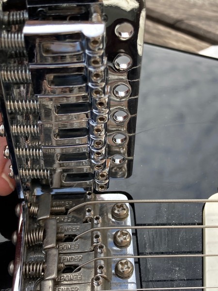
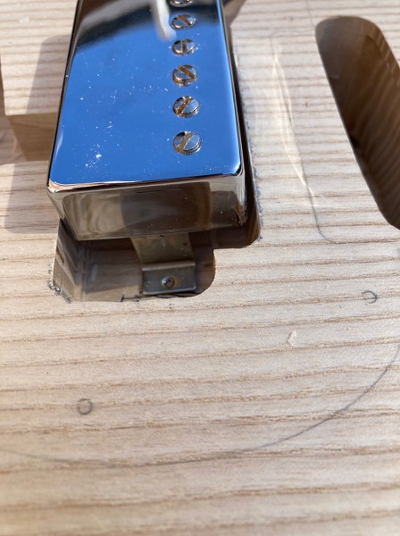
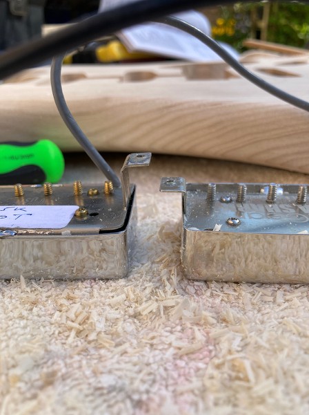
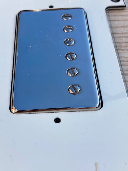
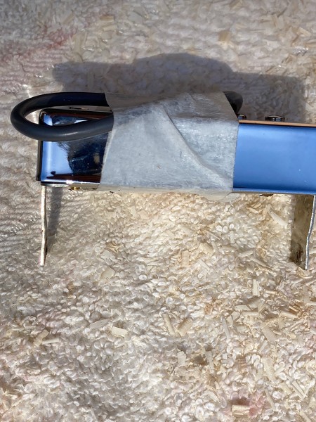
After doing all that, I rubbed off the gold plating on the pole screws on the bridge Gibson 500T, and then fitted a metal cover it. Not forgetting to melt wax in the top of the cover first before soldering it on and then heating it up again in order to stop any microphonics from the cover. I was going to take pics of the process, but I forgot.
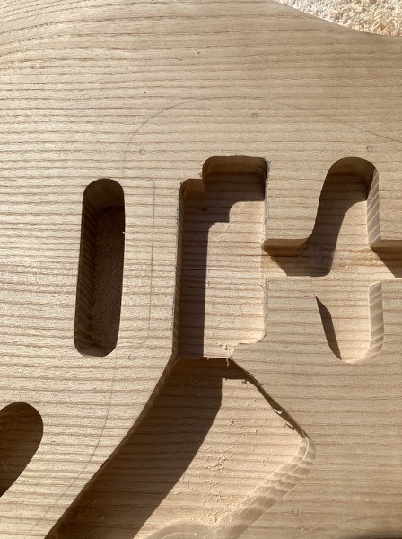
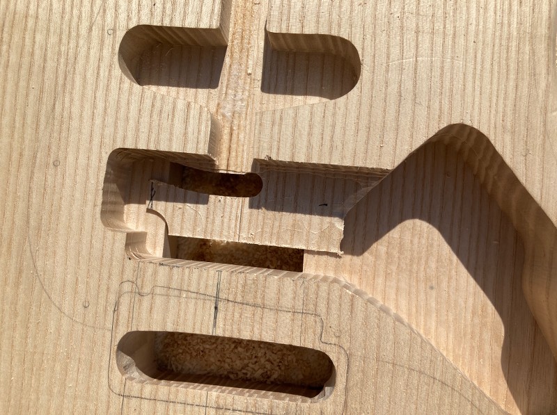
I now need to do some routing, initially so I can fit the humbucker in, but my palm router has gone missing. So I'm awaiting delivery of a new one before I can do too much more.
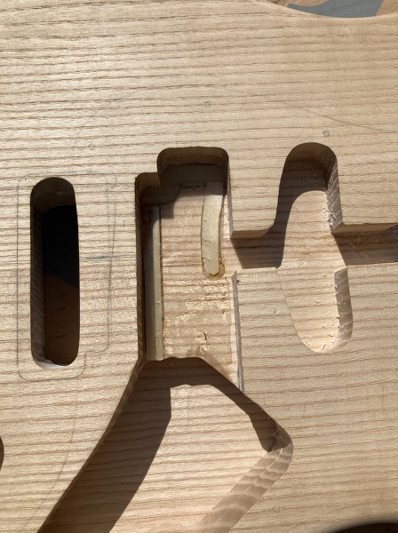
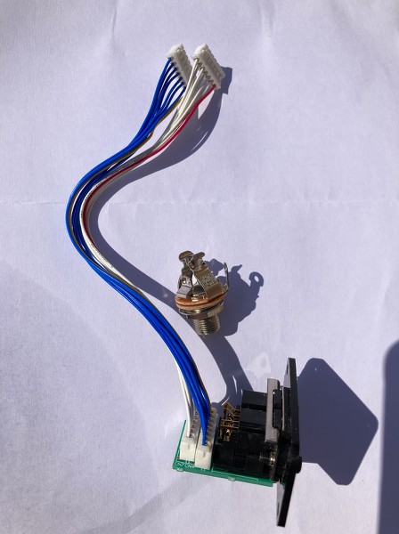
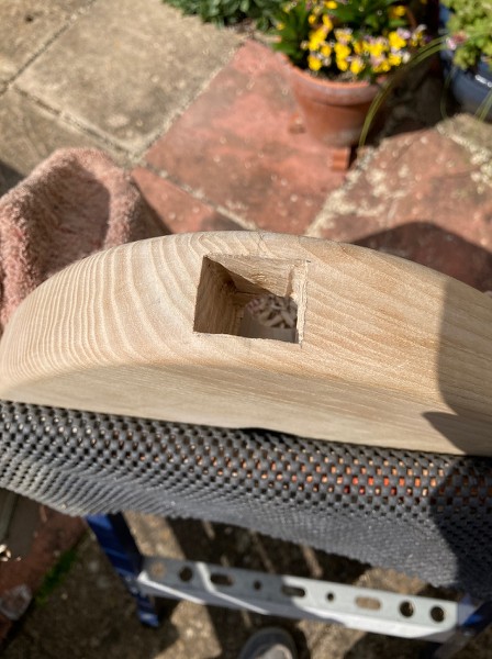
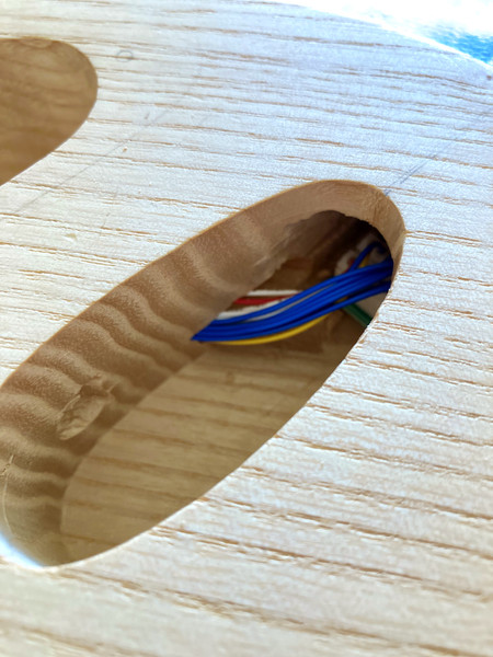
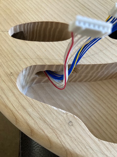
I'll need to drill, rout and chisel a cavity to fit the GK 13-pin connector in, and then try and work out how I can fit the GK board inside the control cavity and still keep the two planned push/pull pots. I'll probably have to rout the bottom of the cavity lower (it's 10mm thick at the moment, so I've got a good 5mm to play with), but the push-on connectors are all vertical and spaced around the edge so need some decent height above to fit in. But I'm hoping that I can arrange the board so the switched pot sits in the centre. Otherwise the switched pot will have to go to reclaim the necessary height.
And I just realised that I'd left some electronics items sitting in a basket rather than checking out, which is why they haven't arrived in the post. D'oh! So just sorted that out.


 Reply With Quote


 ) but I ended up with the existing wood very thin where the front and back cavities over lap. I left as it was since I didn't actually go through to the other cavity, but I'm sure if I poked it hard enough with my finger it would!