
Originally Posted by
Simon Barden

One capacitor is correct for the wiring diagram.
I agree that the kit should have two A500k for volume and one B500k pot for tone. It may be worth checking with a multimeter what the mid turn resistance is on the B pot between the middle tag and one of the end ones. If it is linear, then you should be reading around 250k, if log/audio, either nearer 90k or 410k (depending on the end tag chosen). If B is linear, then email Pit Bull and ask them to send out another A pot. If log, then the A and B designations on the kit pots are simply swapped (annoying but it could happen), so use the Bs for volume and the A for tone.
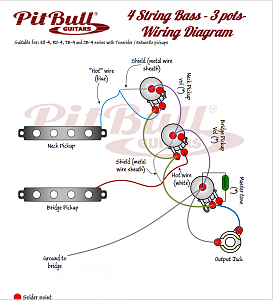
The pickups supplied have 4-conductor wiring, not the 1+ screen shown in the wiring diagram. Unless you feel like wiring the pickup coils in parallel rather than series for a brighter tone, or adding a coil split switch for single coil sounds, you use:
Black - signal hot
Green+screen - signal ground
Red+White - wires that connect the two pickup coils together internally. Leave unconnected and tape up the bare ends to avoid them shorting out. If you want a coil split, then this red/white combo is connected to an extra 2-way switch that can connect the wires to ground.


 Reply With Quote