Cheers for that Marcel, I downloaded a copy of that pdf, I've experimented with the Valvecaster circuit in the past but wasn't able to get it working at it's best, maybe the valves I was using were getting a bit worn out, the circuit tended to be a bit hummy, I'm thinking of building a circuit that uses two 12AX7 valves, but with a higher HT supply that's produced by a square-wave oscillator made from a CD4049 IC that drives a Voltage Multiplier circuit consisting of some 1N4007 (or similar) diodes and some 1uF/100V, or 2u2/100V (can even be some 47uF/100V caps too) electrolytic caps, I found that using the circuit I can easily generate up to something like +90V from a 15V DC supply.
Here's the Voltage Multiplier circuit:
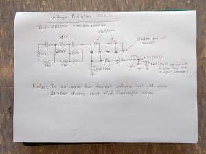
The 10k resistor on the output of the Voltage Multiplier is there just to limit the output current a bit, the square-wave oscillator consisting of the CD4049 IC, 33k resistors, and 220pF cap runs at about 60kHz.
The CD4049 IC has six Inverters in it, three of them are used to form the 60kHz square-wave oscillator and the other three are used as inverting-buffers so that there is enough current drive to drive the Voltage Multiplier section.
I definitely need to get to it and do some breadboarding soon.


Originally Posted by DrNomis_44


 Reply With Quote