Newbie Wiring needing help! No sound when attaching ground wire to jack [ATL-1SB]

Hey team!

I'm working on my first build and have been following all the guides/videos/diagrams I can find.

Now with everything almost done I feel as if I'm stumbling on the final hurdle with wiring the pickups.

I'm following the TL-1 diagram provided on the Pitbull website - https://www.pitbullguitars.com/wp-content/uploads/pdf/PBG-TL-1.pdf

I've just lightly soldered the connections for the purposes of testing, I plan to tidy things up once I can verify everything is working.

The steps I've taken (bearing in mind that this kit comes with a partially pre-wired set of pickups):
  • Connected Neck and Bridge live wires to the 3 way switch
  • Connected Neck and Bridge ground wires to the volume pot
  • Connected live and earth wires to the input jack.

Before attaching the earth wire I can hear a buzz from my amp as expected, when I attach ground there is silence. However when tapping my pickups with a screwdriver (as shown in the Pitbull YT video) I get no sound. I've tried changing the switch to all 3 configurations, triple checking that the volume pot is turned up etc all to no luck.

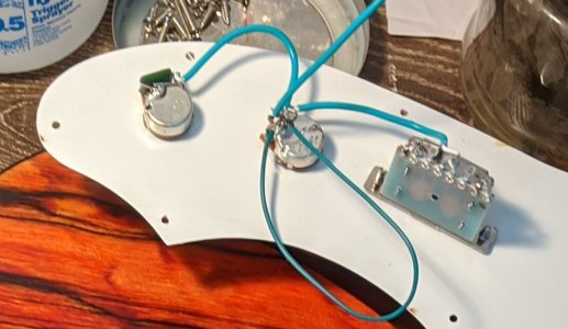
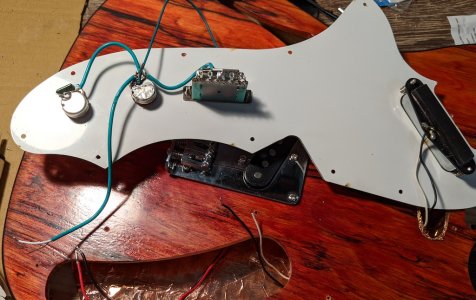
I've attached photos to hopefully help, I'm suspicious that the pre-soldered connections on the volume pot are overlapping.

Images HERE

I'd appreciated any help or advice, I've probably made a rookie error but can't find any other ideas through research.

Cheers
Calum
 
Last edited:
Your connections to the output jack don't look right to me. Conventionally there would be a single shielded cable with the core to the tip and the shield to the rim. I can't see what the shield is doing at the jack end. I suspect your second blue wire is an earth that should go to the bridge. I'm also concerned about loose strands on your pickup wires. I suggest you neaten those up and deal with the loose strands, which have a remarkable habit of finding a way to get in contact with things they shouldn't.
 
Thanks for the response JimC!

I can confirm that there are two separate wires both coming from the volume pot. One seems to have double shielding compared to the other but it does not split into two like I've seen in other setups.

Noted on the looses strands, my intention here was to test out my connections before tidying everything up.
 
Hi Calum.

At the risk of sounding critical, the way the photo is taken is difficult to see how the wires are connected to the pots and what the quality or condition of those connections may be.

Also because you're using shielded wire on connections between the pots & switch, it's possible you've over-heated the braided wire and melted the insulator to the centre wire causing a short. I have done this when I was learning :o.

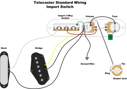
I would suggest de-soldering everything, cleaning up all your connection points (lugs, back of pots) then methodically soldering it all back using single core wire (should have been supplied in the kit) using the diagram I've attached below (the PBG diagram is incomplete for some reason).
By methodically, I mean make your connections in order of the signal path: pickup > to switch > to pots > to output jack. This will help to understand how things should flow so to speak.

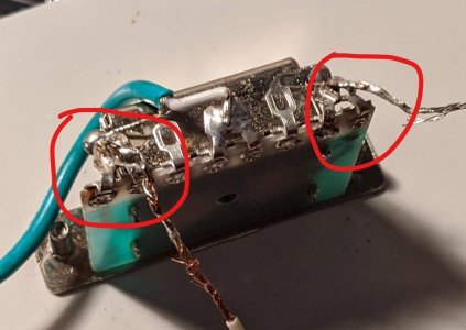
Another tip I'll offer is NOT bending the solder lugs on the switch to jump them as you've done. Jump them with wire. The lugs on those import switches are connected via a PCB and I don't know how robust they are. Bending the lugs sideways like that could possibly bugger up the traces in the PCB leading to connection problems. (that is purely speculation on my part, but I personally wouldn't do it that way). And at least one of the lugs on the switch (outer left in photo) looks like it is burnt at the PCB. Switch could be damaged. (????)

Hope this helps.

3way imp switch TL.jpeg
 
What you should have, I think, is one wire that has both a central core and an outer braid.

At the pot end the core will connect to the middle terminal of the pot, and the braid to either one of the other terminals or the body of the pot, it doesn't much matter which. At the jack end the central core should connect to the tip connector, and the braid to the other terminal.

I can't see clearly, but I suspect the second blue wire is a plain wire with just a core, no braid, and is soldered to the body of the pot. This is almost certainly the earth wire for the bridge, and instead of running to the output jack it should connect to the bridge. Usually there's a hole to underneath the bridge, and the end is splayed out slightly without solder and crushed between the bridge and the body to make a good enough contact.

The little puzzle we have is that whilst bridge earth to jack earth isn't right, it probably ought to work, albeit noisy, so there is something else going on that I haven't spotted from the photos. My first guess is something to do with the screen/shield/braid for the jack connection, which I can't see, and the second would be something bridged at the switch. A close up of the jack might be helpful.

McCreed, my understanding is that the PB diagram only contains the connections that the customer is required to make, the rest is all pre connected, and I assume the shielded cable was supplied with the kit. Although I agree with you that we may come to having to take it all apart and starting again, I'm loathe to suggest it until we have eliminated issues with the jack connections. I do share your concern about the switch, and whether it may have been overheated, but I strongly suggest getting the jack connection right first, and only then working back to the switch.
 
Last edited:
Hey McCreed, thanks so much for your detailed response here!

Apologies on the photo quality, happy to take better angled ones if it helps?

Also because you're using shielded wire on connections between the pots & switch, it's possible you've over-heated the braided wire and melted the insulator to the centre wire causing a short. I have done this when I was learning .

This quite possibly could have happened, I'll check the wires.

Thanks for the full diagram, is super handy to have the full picture. I didn't get a single core wire in my kit but I can pick up some wire at Bunnings.

Regarding the lugs on the switch, it actually came shipped like that and I assumed it was purely to make solder easier? I can look into getting a replacement switch if that might be the problem?

I appreciate the time and effort you put into your reply, this really helps me out! Thanks
 
TBH, it's a bit of a mess, but the clarity of what's going on hasn't been helped by the factory wiring being done in screened cable. It confused me to start with!

Your main issue is that the wires from the pickups are screened cable, that is an inner core which carries the pickup signal, surrounded by a copper braid with the braid being used as the ground connection for the pickup. So it's basically two wires, and you need both wires to be connected to complete the circuit to get a pickup to work.

To do this, the screens need to be connected to ground, which is normally done by soldering them to the back of the volume pot. If you look carefully on the PBG wiring diagram, you can see that the pickup wire splits into two, with the 'hot'/signal wire going to the switch and the 'earth'/ground/screen going to the back of the volume pot in each case.

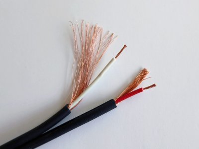
So you need to carefully unsolder the two pickup wires from the switch. The picture below shows what you've got in the pickup cable - the central signal wire and the outer braid.

figure-8-shielded-cable.jpg

You need to get your pickup wires so that the outer braid is first like in the picture, then twist it together so that you can solder it to the rear of the pot. But you also need to leave enough of the central signal wire so that it's long enough to reach to the switch with all of its insulation intact, apart from a short stripped length which you will solder to the switch.

It also looks like that you hadn't linked the two outer tabs on the switch together like in the diagram. If you don't do this, you won't get any sound with the switch in the middle position. You would normally just pass one end of the signal wire through the hole in the outer tab, then push it through the hole in the inner tab, then solder the wire to both tabs. You can use a separate piece of wire to link the two tabs, but it is easier to do it with the signal wire.

You really do want to keep the insulation on the signal wire all the way to the switch, as the body of the switch is grounded, and if bare signal wire touches the body, then you'll get no signal.

The switch you've got with the kit is slightly different to the one shown in the PBG wiring diagram WRT the number of tabs on it, but link the two end tabs at each end and you'll be fine.
 
Ok I think I have a wire that has a central core attached to the pot, funnily enough it appears that the other end is partially stripped and tinned so I'll just need to cut it shorter.

Ok great, I was wondering about the bridge wire, that's good to know I'm using it incorrectly.

After McCreed's comment I'm suspicious about whether or not the switch is faulty.

Thanks for the advice, I'll try out your suggestions. Cheers!
 
Also because you're using shielded wire on connections between the pots & switch, it's possible you've over-heated the braided wire and melted the insulator to the centre wire causing a short.

That wiring is the factory supplied wiring, so I'd leave that as it was. The only connections that need to be made with the kit are the two pickup wires to the switch and back of the volume pot, so just concentrate on those for the moment and assume the factory wiring bit is correct. As McCreed says, it would be a lot easier to follow had the factory used single core wire for the pot wiring, but it should work fine once you get the pickup wiring sorted.
 
Simon, you reckon the coloured pickup leads are screened then? I interpreted the photos as being that the red and brown were single core hot, and the cold connections were the black ones going back to the volume pot.

The blade switch is very odd, have you seen one with 8 tags like that? It seems to have two centre tags soldered together at the factory, and two outer ones soldered together.
 
Ok I think I have a wire that has a central core attached to the pot, funnily enough it appears that the other end is partially stripped and tinned so I'll just need to cut it shorter.
NO!
Don't do that.
The blue earth wire needs to be taken off the output jack completely, and that stripped tinned shield wire soldered in its place.


BTW, as a general tip, I don't suggest lightly connecting the wires for testing. Connect them up as you mean to leave them.
Several reasons, but among them are
Once you have it working you really don't want to take it apart again and maybe get it wrong the second time.
It tends to be a lot more fiddly to reconnect wires that have already been soldered to tags that have already been soldered.
Modern plastic based components are prone to melt if overheated, so the fewer times you solder to them the better.
Connecting up less neatly for testing means its more likely something will go wrong.
 
Last edited:
Having just had a look at your second picture, forget about what I said about the switch linking as it is the same as in the PBG wiring diagram and either you or more likely the factory have bent the two outer lugs together. It's not a good way to do it, but it's been done, so leave it as it is if it works. So just sort out those pickup signal wires, attach the ends back onto the switch once you've sorted out the braid, and you should be good to go.

Inkedswitch_LI.jpg
 
NO!
Don't do that.
The blue earth wire needs to be taken off the output jack completely, and that stripped tinned shield wire soldered in its place.

NO! Please don't do that.

Jim is easily confused. The factory wiring looks OK. Pickup wire connections only.
 
The blade switch is very odd, have you seen one with 8 tags like that? It seems to have two centre tags soldered together at the factory, and two outer ones soldered together.

8 tag switches like that are common, though they are normally 5-way switches. The factory bending and soldering is a bit weird though. I just hope it is a 3-way and not a 5-way switch.
 
Holy crap!!! That wiring from the pots to the switch is factory????
Wow, I've never anything like that before. Even in the lowest budget manufactured guitars.
And the bent lugs on the switch, yikes... sorry for presuming you did that Calum!

re: the pickup wires, I'm pretty sure the leads coming off the pickups are two single core. I think the bridge pickup has red (+) and black (-) and neck is white & black.
 
Simon and I differ on the interpretation of the photo. AIUI he reckons your red and brown (or maybe its white) pickup wires are shielded with an outer braid/screen as per his photo and a separate inner core with its own insulation. That would be conventional, but I reckon that they are single unshielded wires, without the separate shield and core, and the second wires from the pickups are the black ones. This is a vital distinction!
The kit contents photo shows the pickups with yellow shielded cable, and a bundle of loose cable. Did it come like that? Are there any cable joins we can't see in your photo?
 
Last edited:
Having had another look, I do think Jim's right here. Those wires to the switch are singles. I was seeing what I expected to see. D'oh!

So the pickup wiring to the switch is probably 'right', but certainly needs to be tidied up as there shouldn't be those lengths of bare wire around.

Calum, can we have confirmation that the pickups have two single core wires from each pickup (one red and black pair, the other a brown and black pair)? I just haven't seen two singles being used on kit pickups, even though that's how Fender would do them.
 
Not that it matters, but I see red and *white* as the positive lead colours.

The ATL-1SB kit shown at PBG, says:
"Hardware options available in Chrome or Gold, with a Pearloid pickguard, which has been pre-loaded with 1 single coil pickup, plus a Control Panel with 1 Tone, 1 Volume and a 3 way switch."

Doesn't show the pre-loaded neck pickup but, the bridge pickup in the photo clearly shows it having 2 single core leads. 1 red, 1 black

This ones a bit of a head scratcher...

ATL-1SB @ PBG
 
Thanks all for the comments!

To clarify a few things:

All 4 pickup wires are single core

Bridge = Red and Black
Neck = White and Black

I have a picture of the pickup setup when it arrived.
IMG_20191208_092505.jpg

I've removed all current work, and reverted back to the state where I have done no additional soldering. Also tidied up the wires as advised. Picture below (let me know if you need a higher res)
IMG_20191210_182636.jpg
 
Back
Top