Page 1 of 14 1 2 3 11 ... LastLast
Results 1 to 10 of 132

Thread: A quick tube (valve) fuzz box

  1. #1
    Mentor
    Join Date
    Aug 2013
    Location
    Mackay
    Posts
    1,276

    A quick tube (valve) fuzz box

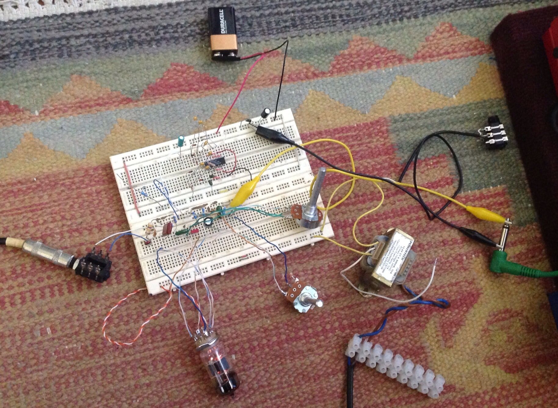
    Well, as you are probably aware, I can't get stuck into my fretless build because of cyclone Dylan cleanup. So I decided to design/build a quick valve fuzz pedal on breadboard this afternoon using some bits I have lying around. I love designing valve stuff for guitars, they always sound so cool 8-) For those who are interested, it is a starved plate design using a 12AU7 and powered from 12 volts. I used a 12 volt transformer but a 12VAC plug pack would do. The 12 VAC power goes through a voltage multiplier to lift the plate voltage to around 50 volts and also feeds the valve heaters. This circuit has a tone control but I probably shouldn't have bothered. Anyway, it sounds pretty damn cool. I may just stick it in a box and use it on my pedalboard.
    The 9v battery was removed in the final setup. It was just there in case the 12VAC was too noisy - but it wasn't

  2. #2
    Mentor AJ's Avatar
    Join Date
    Mar 2013
    Location
    Hoppers Crossing, Melbourne
    Posts
    562
    Wow.. Lawry.. cool!
    Can you do a reverb unit like that?
    Projects:
    LP-1A
    TL1-A
    LP-1Completed
    TL-1Completed
    Yamaha rebuild: Completed
    Mako -Scratch designed: Completed
    PUP winder: Completed

    Facebook : www.facebook.com/andrew.johns.1272010
    Skype: andyjohns1

  3. #3
    Mentor
    Join Date
    Aug 2013
    Location
    Mackay
    Posts
    1,276
    Hey AJ. Reverb units need a bit more circuitry, much higher voltage (~300VDC or more) and higher current for the spring's driver transformer. It's doable, but it's not a quick or cheap project. Sorry man, if you were after an inexpensive knock-up reverb, it ain't that easy. However, this project only has about $50 in parts and you end up with a real valve distortion/overdrive unit.

  4. #4
    GAStronomist stan's Avatar
    Join Date
    Aug 2013
    Location
    Geelong, Vic
    Posts
    5,290
    that is awesome Lawry - you need to do a sound clip with it set up just like that

  5. #5
    Member
    Join Date
    Aug 2013
    Location
    Adelaide
    Posts
    35
    Lawry this looks real interesting to me. Could you post a schematic and parts list? I've built all sorts of gadgets and test boxes for work over the years but never anything with a valve in it. I'm guessing the starved plate design is creating distortion by running the valve at a lower than normal voltage? Stan's right - we need audio!

    I passed through Mackay on the way up to Cairns last April - beautiful part of the world for sure. Hope old Dylan hasn't left too much of a mess and you can get back to guitar building soon.

  6. #6
    Overlord of Music
    Join Date
    Aug 2012
    Location
    Brisvegas
    Posts
    3,356
    Nice one Larry, building pedals is something that I've wanted to do for a while. I found this website a while ago and their kits look great but I've yet to take the plunge.
    http://buildyourownclone.com/
    'As long as there's, you know, sex and drugs, I can do without the rock and roll.'

  7. #7
    C'mon Lawry, you know the rules... schematic or it didn't happen

    Scott.

  8. #8
    Mentor
    Join Date
    Aug 2013
    Location
    Mackay
    Posts
    1,276
    OK Guys,
    I made a couple of small changes to the circuit since I posted it yesterday in order to make it easier for anyone who wants to build one. Nothing major, just swapped out the active multiplier for a passive one and removed the tone control. As requested, here are some sounds, and seeing how I always call my 'brand' Dirty Angel, it seemed appropriate to give the pedal a demonic name. Hence it is called the Purgatory Pedal. The guitar used is my Dirty Angel 'Viking' RC-1 build and the recording was done straight from the pedal into a Presonus 1818VSL USB Audio interface. The recordings are completely dry except for the pedal. Now, on to the sounds...
    First 30 seconds is a clean reference signal using the bridge pickup.
    The next 30 seconds is the bridge pickup with the gain on 3.
    The next 15 seconds is the neck pickup with the gain on 3.
    The last 30 seconds is the neck pickup with the gain on 7.

    Above 7 the whole thing just gets muddy.
    I recorded some sounds this morning and placed the file here...

    https://soundcloud.com/dirty-angel-2...-pedal-samples

    Yep. There was a schematic here but it had a an error (forgot to delete a bit when I changed to the passive voltage multiplier) so I removed it so that no one would use it and get it wrong. I've redrawn the schematic and will post it soon along with a vero board layout.

  9. #9
    Mentor AJ's Avatar
    Join Date
    Mar 2013
    Location
    Hoppers Crossing, Melbourne
    Posts
    562
    sound terrific Lawry !
    Projects:
    LP-1A
    TL1-A
    LP-1Completed
    TL-1Completed
    Yamaha rebuild: Completed
    Mako -Scratch designed: Completed
    PUP winder: Completed

    Facebook : www.facebook.com/andrew.johns.1272010
    Skype: andyjohns1

  10. #10
    Very nice.


    Scott.

Page 1 of 14 1 2 3 11 ... LastLast

Posting Permissions

  • You may not post new threads
  • You may not post replies
  • You may not post attachments
  • You may not edit your posts
  •