
Yes, but don't forget to put a bit of heatshrink tube over the join.


Yes, but don't forget to put a bit of heatshrink tube over the join.
Build #1, failed solid body 6 string using neck from a scrapped acoustic (45+ odd years ago as a teenager!)
Build #2, ugly parlour semi with scratch built body and ex Peavey neck
Build #3, Appalachian Dulcimer from EMS kit
Build #4, pre-owned PB ESB-4
Build #5, Lockdown Mandolin
Build #6, Sixty six body for Squier
Build #7, Mini Midi Bass
Build #8, Acousticish Telecasterish Guitar

You can do it that way, but if I were doing it, I would use a longer piece of single conductor shielded wire (just like the red one you have - but longer). In a hollow body, the less loose wires you have inside, the better. Also you gain the shielding affect of the braided portion (also acting as your ground).So for both wires (ground and normal) its ok to just solder a normal bit of wire to each to make up the length?
However, if you only have single core wire at your disposal, you can do it as you suggested.
If you do use two separate wires, be sure and do this:
- insulate the solder joins (as Jim said). Preferably with heat shrink tubing not tape.
- after you've soldered the extensions on and insulated the joins, twist the 2 wires into a helix formation and shrink some tubing over the helix before you solder to the output jack terminals. Just be sure to leave enough "untwisted" that you can freely solder the ends.
Doing the second step will keep things tidy and give the benefit of acting like a shielded coaxial cable. (like "twisted pair" mic & instrument cables)
Good luck and happy soldering!
Edit: Just wanted to add, the twist in the 2 wires doesn't need to super tight, just kind of a moderate helix, if that makes sense.
Last edited by McCreed; 07-03-2020 at 05:31 PM.
Making the world a better place; one guitar at a time...
Do you mean replace the whole wire with a longer one?? And how would I get the ground wire too? Or does that come in certain wires already?Originally Posted by McCreed

Sorry Ive never done any electrics before so have no idea about this!
YesDo you mean replace the whole wire with a longer one??
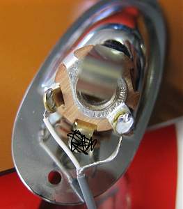
The red wire that came with the kit (the one that's too short) is known as "single core shielded wire" (or cable).And how would I get the ground wire too? Or does that come in certain wires already?
It has the inner insulated wire (the "single core") next there is the braided wire (the "shield") and last is the outer insulation (the red pvc).
The single core is your positive (or "hot") lead that goes from the middle terminal of the 3-way switch to the "tip" terminal of the output jack.
The braided shield is also your negative (or "ground") which goes from the big lug (opposite the 3 positive terminals) of the 3-way switch to the "sleeve" terminal of the output jack.
NOTE: The photo shows a 3 terminal jack. Just ignore the middle one and look at the wire.
Last edited by McCreed; 08-03-2020 at 07:07 AM.
Making the world a better place; one guitar at a time...
Amazing thanks for that idiot proof explanation (it was much needed)!!!! Now to find some single core shielded cable!!
Hi chaps, I hope youre all staying healthy!
So Im in wiring hell!!! Ive basically rewired the whole thing and cant get any output from the bridge pickup...Ive followed the wiring diagram and cant spot any mistakes but still nothing!
And weirdly when I select the middle position (both pickups) I get no output either?? The neck works fine when in the rhythm position but nothing in middle or treble positions...PLEASE HELP!!!!
Ahahahahaha!
Thanks again!
Oh my god call me Leo Fender I think I fix it...hahahaha!

Just re-soldered it and it worked!
Hmmm chaps Ive hit quite a sizeable stumbling block...
Ive got my bushings in for the bridge and the stop bar fits fine BUT the actual bridge bit doesnt fit. Once you screw the poles in theyre too close together!
Obviously when I fitted it at the beginning with foam around the poles it must have been pinching in a bit and I didnt notice!
Am I screwed now or is there a fix that doesnt involve trying the get the bushings out as they were a really tight fir and Im not sure theyll come back out!
 Posting Permissions

 Reply With Quote