Results 1 to 8 of 8

Thread: DMS-4 Bass wiring help!

  1. #1

    DMS-4 Bass wiring help!

    Hi,

    I am currently building my first guitar with my 14 year old daughter, which is a DMS-4 Bass guitar.

    I have thoroughly searched through the guides and cannot find any related to the DMS-4. The YB4 wiring diagram is the closest I can find to what I have. The issue with this is it shows an earth wire to the bridge but I don't have that option to wire the bridge.

    I am also missing the tone, volume and jack components, so I will have to purchase some of those.

    Please if there is anyone who can advise where I can get a wiring diagram from, I will be forever grateful.

    Also note, I am not musically gifted (that is my daughters gift) so I may need some layman's terms at times.

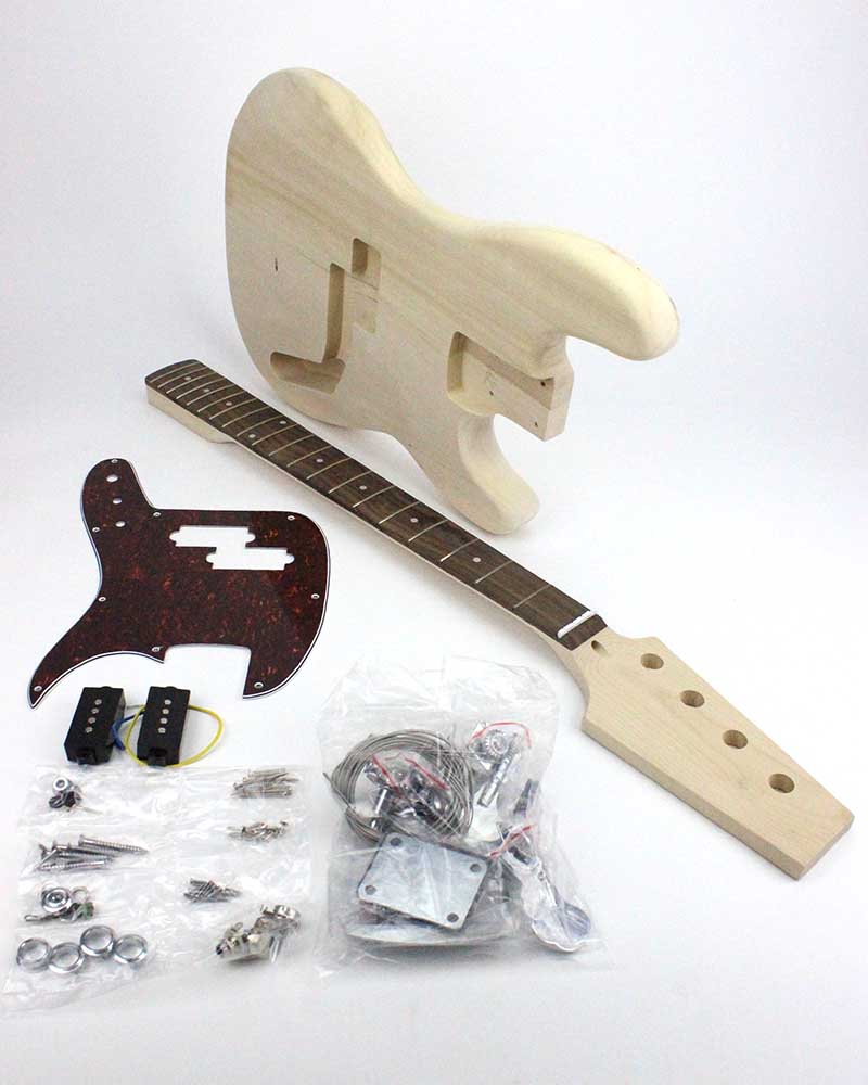
    I have attached a photo of where I am up to with the build.

    Click image for larger version. 

Name:	20191013_104001_resized-1058x1411.jpg 
Views:	170 
Size:	198.2 KB 
ID:	32450
    Last edited by basham75; 13-10-2019 at 10:52 AM.

  2. #2
    Member Cliff Rogers's Avatar
    Join Date
    Aug 2019
    Location
    Minbun, FNQ
    Posts
    234
    Cliff

  3. #3
    Overlord of Music WeirdBits's Avatar
    Join Date
    Jan 2013
    Posts
    2,731
    The DMS-4 is a little different from a standard PJ layout as it has 1 Volume, 1 Tone and a 3-way toggle, so this wiring diagram is a good match. Different pickups etc. but the connections are the same, although you should use 250K pots (log/audio taper) instead of 500’s.

    Regarding your Bridge ground connection, was there not an angled hole drilled under where the bridge sits? It usually looks a bit like a gouge in the body. Like this:
    Scott.

  4. #4
    Quote Originally Posted by WeirdBits View Post
    The DMS-4 is a little different from a standard PJ layout as it has 1 Volume, 1 Tone and a 3-way toggle, so this wiring diagram is a good match. Different pickups etc. but the connections are the same, although you should use 250K pots (log/audio taper) instead of 500’s.

    Regarding your Bridge ground connection, was there not an angled hole drilled under where the bridge sits? It usually looks a bit like a gouge in the body. Like this:
    Hi Scott,

    Mate you are a legend, thank you so much.

    Yes the gouge is there, I actually thought it was a flaw in the wood., but it doesn't go anywhere. Any ideas?

    The sentence about pots, I am unsure what you mean.

    Anyway, I have most of the info to finish the job so I can keep going.

    Thank you again.
    Last edited by basham75; 13-10-2019 at 01:50 PM.

  5. #5
    Moderator Brendan's Avatar
    Join Date
    Apr 2013
    Location
    Perth, WA
    Posts
    3,444
    Try feeding a wire from the hole underneath the bridge to see where it goes - it should reach into the control cavity. If you don't put the bridge wire in, you can end up with some issues with a hum from the guitar when it's plugged in unless someone touches the strings.

    The kit should have come with potentiometers and capacitors (pots and caps) in a bag with all the screws. (See the bag at the bottom left of this image - looks like the pots are in the bottom right partition of the bag).


  6. #6
    Quote Originally Posted by Brendan View Post
    Try feeding a wire from the hole underneath the bridge to see where it goes - it should reach into the control cavity. If you don't put the bridge wire in, you can end up with some issues with a hum from the guitar when it's plugged in unless someone touches the strings.

    The kit should have come with potentiometers and capacitors (pots and caps) in a bag with all the screws. (See the bag at the bottom left of this image - looks like the pots are in the bottom right partition of the bag).


    Thanks Brendan,

    I did try putting several different wires through it, but it wasn't drilled all the way through. A trip to bunnings for a XL drill bit and I drilled the hole right through. Close to finishing now.

  7. #7
    Overlord of Music fender3x's Avatar
    Join Date
    Jan 2016
    Location
    Miami, FL, USA
    Posts
    2,201
    Here's a pic of a wiring pattern that should fit your components.

    Click image for larger version. 

Name:	mustang2017.jpg 
Views:	738 
Size:	92.8 KB 
ID:	32462

    This is from Cadfael's book on bass wiring. The kit is a near copy (I think) of the Fender 2017 Mustang. This shows how these Mustangs were originally wired. Almost all of this is in English.*

    This diagram shows the original values. As Weirdbits has guessed, the pots are 250K. This diagram also shows the switch that goes in the lower horn.


    * The parts in German are pretty simple... "Masse" is "ground" or "earth." "Spitze" is "tip." "Schaltplan" is "wiring diagram." "Saitenerdung" is "string grounding", "Kabel zum Steg" is "wire to the bridge".
    Last edited by fender3x; 13-10-2019 at 09:30 PM.

  8. #8
    Overlord of Music fender3x's Avatar
    Join Date
    Jan 2016
    Location
    Miami, FL, USA
    Posts
    2,201
    One small difference between your bass and the original Mustangs is that the original Mustangs had a metal control plate (like a Jazz bass). So, it didn't need to run a ground (earth) wire between the pots and the jack. This is reflected in the chart above with a dotted line. You will probably want to use an actual wire to do this, since your pots and jack attach to a plastic scratch guard.

Posting Permissions

  • You may not post new threads
  • You may not post replies
  • You may not post attachments
  • You may not edit your posts
  •