Dear All
The JM1 pick guard and tone knobs come pre-loaded and soldered but has anyone got any idea how to connect it all together?
Thanks


Dear All
The JM1 pick guard and tone knobs come pre-loaded and soldered but has anyone got any idea how to connect it all together?
Thanks

This may help.
And, from the wiring guides section, this image should put the linked post in context.
Scott.

Peter - any chance of a slightly better photo of the control plate? I can probably draw something up for you - just need to know where you're starting from. Mainly want to see where the light purple and the white from the 4 wires connect to.
Cheers.
Current builds:
GPB-4B: https://www.buildyourownguitar.com.a...548#post184548
Brendan, from Peter's photo it looks like his is set up as (I think):
single black wire: tone 2 pot casing --> bridge ground
blue wire: jack ground lug --> pot casing grounds --> switch ground lug
purple wire: volume pot right lug --> switch centre lug (switch output)
white wire: tone 2 pot left lug --> switch left outer lug (bridge tone)
grey wire: tone 1 pot left lug --> switch left inner (both) lugs (middle & neck tone)
Caps link the middle lugs of the tone pots to their casing, and another white wire connects the middle lug of the volume pot to the tip lug on the jack.
For the pickup connections on the switch, bridge hot = right inner lug, middle hot = right middle lug, neck hot = right outer lug, with the grounds connected to the switch ground lug.
(left and right are relative to Peter's photo)
But, it seems like the factory wiring for the JM's has changed over time, and the colour coding could vary between different batches of kits so a diagram may not always match up completely.
Scott.
Gents. Thanks for replies but need more help because I know jack about wiring guitars. I have attached some slightly better photos. Murphy's law states that photos of wiring looms will never be in focus. Here are some notes that might help.
Yes a blue wire has come away from the input jack lug
Black wire to ground on bridge
The wire coming away from pot closest to jack is white
Wire coming away from middle pot is grey
There are two wires coming away from pot furtherest from jack blue and purple. Blue from casing (ground) and purple from left hand lug
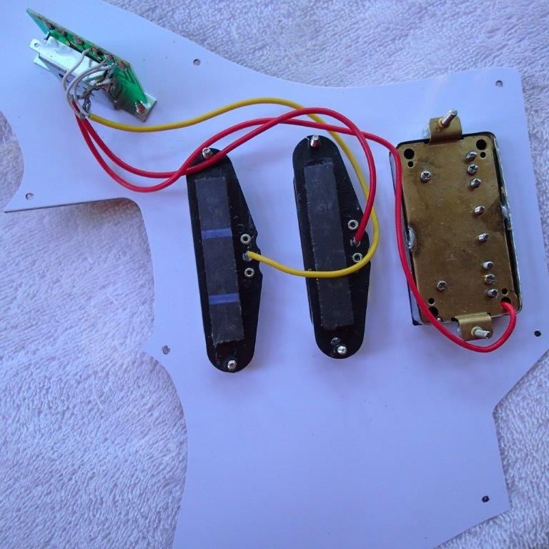
The PUPs connect to switch as follows
Humbucker 3rd from right
Middle 2nd from right
Neck last on right
Hope this helps and thanks in advance
Peter, hopefully this will sort you out.
First up, the control plate
Connect the black ground wire to your bridge/tremolo, and reconnect the blue wire to the jack's ground lug (as indicated):
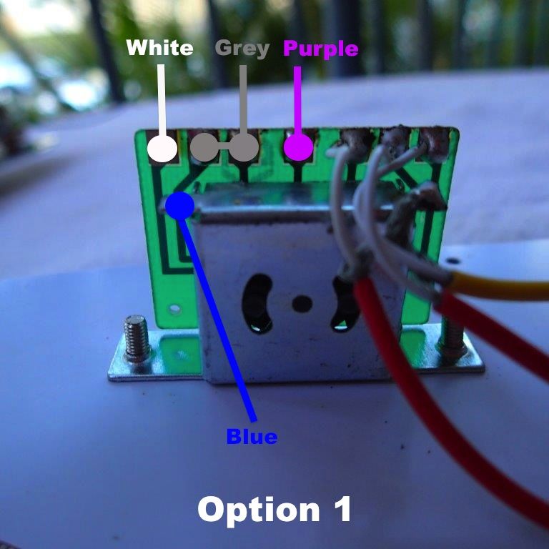
For the bundle of 4 wires (grey, white, blue and purple), you have two options with how to connect them to the switch. Basically, how you want your tone controls to work. The blue wire is the ground link to the switch body, the purple wire is the switch output, and the white and grey wires are the tone connections. The 'dots' are the solder points.
Option 1:
Tone 2 = Bridge pickup, Tone 1 = Middle & Neck pickups (the grey wire needs to connect across both points). Given that the bridge pickup is a humbucker, this is probably the most useful setup.
Option 2:
Tone 2 = Middle pickup, Tone 1 = Neck pickup, Bridge pickup has no tone control. This is more a traditional Strat type setup where the bridge pup doesn't have a tone control.
A potential third option would be the same as option 1 but to not link the grey wire to the middle contact, which would give you: Tone 2 = Bridge pickup, Tone 1 = Neck pickup, and no tone control for the middle pup.
Just pick the option you want and connect the wires accordingly. If you need any more help let us know.
Scott.
Weirdy, you are definitely the wiring guru!

gee coming from Lozza ! I agree Weirdy is deffo the best forum wiring guru without doubt.
Current Builds and status
scratch end grain pine tele - first clear coat on !
JBA-4 - assembled - final tweaks
Telemonster double scale tele - finish tobacco burst on body and sand neck
Completed builds
scratch oak.rose gum Jazzmaster - assembled needs setup
MK-2 Mosrite - assembled - play in
Ash tele with Baritone neck - neck pup wiring tweaks and play in
Thanks guys - will get to work on a diagram. Remember - if there is a diagram that we're missing, send me some photos and I'll try and get one up - I just don't have one of each kit at home to check all the parts are the right ones.
Current builds:
GPB-4B: https://www.buildyourownguitar.com.a...548#post184548
Thanks for all your help guys. WeirdBits you the man!
 Posting Permissions

 Reply With Quote