
At the risk of throwing spanners in, you could have 4 push pull pots then for your volumes and have each coil individually on/off instead of the rotary.


At the risk of throwing spanners in, you could have 4 push pull pots then for your volumes and have each coil individually on/off instead of the rotary.

Haha yeah I could, but I don't like them much, I'm used to the click of an upper switch!
I'm trying to find a good switch on Mouser, is it 6 positions, 3 decks and 2 poles per deck?

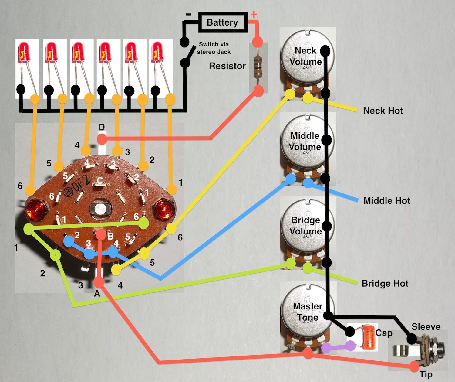
Here ya go Pest, I think this should work. Although, I suspect the LEDs will prove to be more trouble than they're worth in the long run.
The resistor's value will depend on the LEDs you're using, how bright you want them, and the battery voltage. It may be better to use a couple of AA batteries so you so don't have to drop as much voltage across the resistor. You will need some type of on/off power switch for the LEDs, so a stereo/switched jack will probably be the simplest option. Lawry will be the best to offer advice regarding the LEDs etc.
The wiring below has a volume for each pickup and a master tone, with the following configuration:
1. Bridge
2. Bridge & Middle
3. Middle
4. Middle & Neck
5. Neck
6. Bridge & Neck
I didn't have a stereo jack on hand, so just imagine there's also a 'ring' lug on the jack (for the battery switching). As always, caveat emptor.
Scott.
That's excellent Scott. I've just read this thread for the first time and was almost heading for the pad and pencil. Fortunately, you've done it and saved the last relic of sanity of this old man.
Sad as it may seem, I'd love to spend an arvo with you drinking beer and designing stuff. God knows what we could come up with. After all, the aural exciter was discovered from an electronic build stuff up.

Lawry and Weirdy in the same room, drinking beer and designing stuff?
That could be dangerous... probably end up perfecting the Brown Note weapon!
There is always a workaround for glitches, mistakes and other Guitar building gremlins.....
Dangerous indeed, mostly from my severe lack of knowledge.
But, I was just thinking...
As there is a spare pole on the switch, instead of using 6 LEDs for the six positions, we could instead have one LED per pickup mounted in the pup's ring to show which are active. To make it easy it could have a 4th LED as a dummy parallel load hidden in the cavity, that way we could have two parallel LEDs active at all times (the dummy load would be used for positions 1, 3 & 5) and stick with just a single resistor to set the voltage. Thoughts?
Edit: Actually, scrap the above. Just use three LEDs: one fitted in each pickup ring to show if the pickup is 'on'. It would just require a resistor on each of the 3 LEDs instead of single resistor, but I sure Pest could handle it, and of course there would be a slightly increased current draw whenever two pickups were selected. But, assuming the LEDs are reasonably bright, you would always be able to see your pickup selection without even looking at the rotary switch.
Lawry, sounds like a great way to spend an arvo... sadly, it's a long way for a beer.
Scott.
/<\\/p>[]<\\/p>/Quote from WeirdBits on April 29, 2014, 19:20
Dangerous indeed, mostly from my severe lack of knowledge.
But, I was just thinking...
As there is a spare pole on the switch, instead of using 6 LEDs for the six positions, we could instead have one LED per pickup mounted in the pup's ring to show which are active. To make it easy it could have a 4th LED as a dummy parallel load hidden in the cavity, that way we could have two parallel LEDs active at all times (the dummy load would be used for positions 1, 3 & 5) and stick with just a single resistor to set the voltage. Thoughts?
Would that be for an inbuilt Brown Note function? :P
There is always a workaround for glitches, mistakes and other Guitar building gremlins.....

Mix the Weirdbits, Lawry and Pest and it really gets weird. I for one am closing my ears for fear of the brown note!
Current builds:
GPB-4B: https://www.buildyourownguitar.com.a...548#post184548
@Scott. The idea of a ring of LEDs around the pup ring sounds cool to me. I like that idea.
@the rest of you. I don't think we need a brown note generator when there appears to be enough brown stuff going around here at the moment

Just a random thought, have you seen the Peavey vypyr's knobs?? They have a ring of leds which light up showing which position the thing is in and its pretty cool. If you could get your hands on one of those, it would just be like wiring up a normal rotary and the leds would be done for you.
 Posting Permissions

 Reply With Quote
![[url=https://www.facebook.com/kellysgutiars]](image.php?s=065b2164d6dbf8c37e42786f969655e5&u=1285&type=sigpic&dateline=1444110346)
