Sounds sweet Lawry, just tweaked my interest. Have been contemplating a valve amp build down the track this may be a nice fill in.
May have some questions for you down the track when I can spend some time checking your circuit diagram.


Sounds sweet Lawry, just tweaked my interest. Have been contemplating a valve amp build down the track this may be a nice fill in.
May have some questions for you down the track when I can spend some time checking your circuit diagram.
Thanks for posting the circuit Lawry. It sounds great! Reckon I might have a crack at building one of these in a couple of months.
@Kane building this would be a great warm up to building an amp.
Thanks to all for your comments. I really built this out of frustration because I couldn't do any work on the guitar and needed to do something.
This circuit is a nice intro to valves and the voltage is safe, whereas a full-on valve amp can kill you before you even know you're dead if you're not careful. That doesn't mean you shouldn't build one, just be very careful. Especially if you're unfamiliar with high voltage electronics.
@Kane. Ask anything you like.

love the sounds Lozza, you really are an electronics guru !
nice axe playing too !
setting on 7 is heavy enough and sustain is good !
Current Builds and status
scratch end grain pine tele - first clear coat on !
JBA-4 - assembled - final tweaks
Telemonster double scale tele - finish tobacco burst on body and sand neck
Completed builds
scratch oak.rose gum Jazzmaster - assembled needs setup
MK-2 Mosrite - assembled - play in
Ash tele with Baritone neck - neck pup wiring tweaks and play in
Thanks Wokka. Agreed, the sound on 7 is as heavy as you need. Seriously thinking about buying a box and making it permanent pedal and If I do I'll probably put it on vero board. And if there's enough interest I'll post the layout for those who want it. We'll see.
Cool job Mate...
if you can do a track layout I can machine a couple out for ya, using this stuff
http://www.ebay.com.au/itm/Single-Si...00423049476%26
I rekon you put a little kit together a few blokes will have one in a heartbeat! not that you have enough to do already hey! tehe!
A CNCed PCB eh? I've etched a sh!t load over the decades but never had one ground away before. I'll think about it though.
The circuit is so simple that vero makes an accessible option at any time. But a 'limited edition' version does sound kinda cool.
Thanks
Right then. It is absolutely @issing down here today with thunder and lightning aplenty. So it seemed like a good idea to finalise this project.
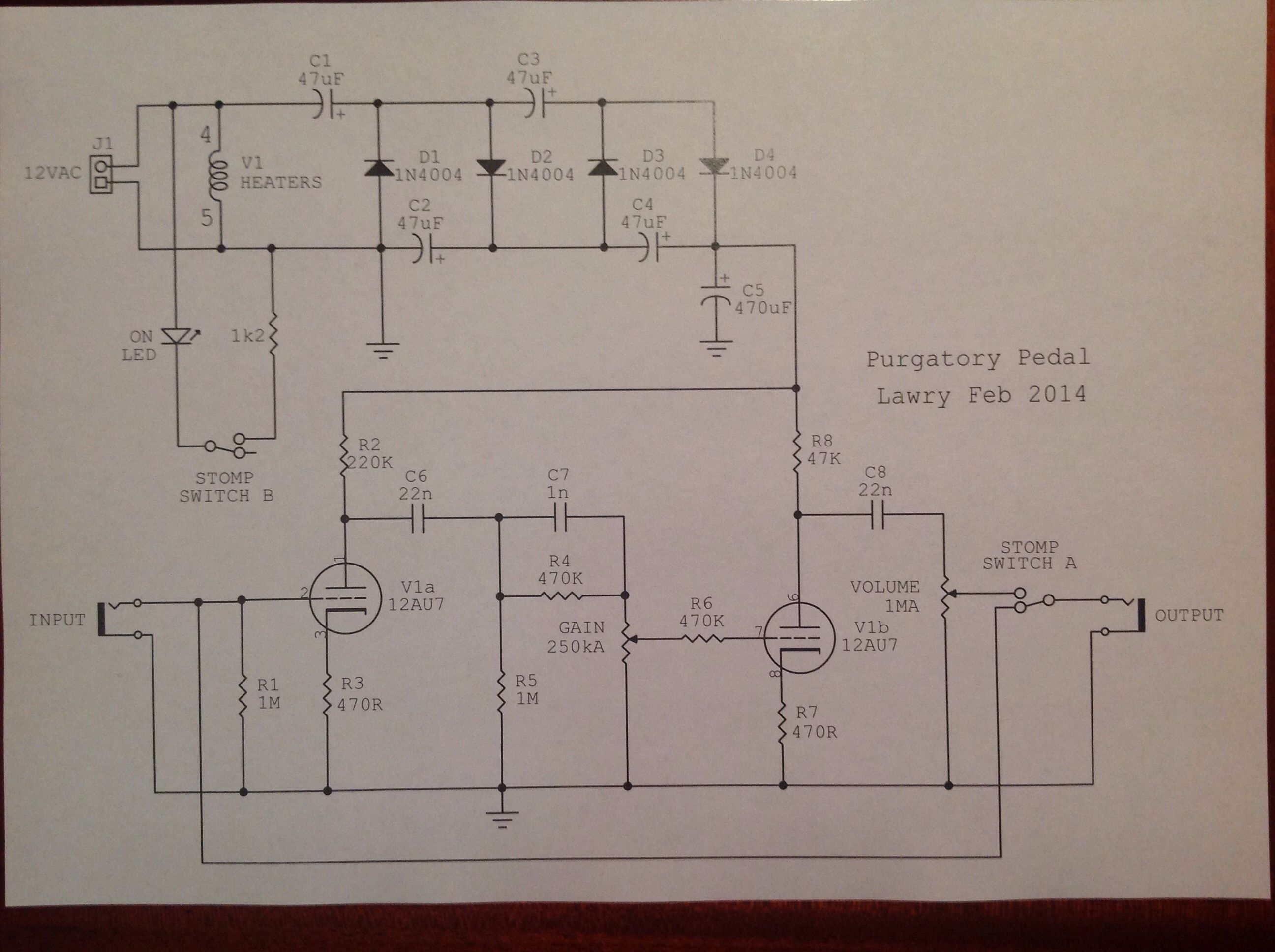
I have fully drawn the final schematic (and hopefully correctly), drawn up a vero board layout, then built and tested the end design. Needless to say, it sounds exactly like the previous clips. For those of you who want to build it there are a some important things to know.
1) the original design (and indeed mine) shows the 47uF capacitors as 63 volts. I recommend 100 volts because when I checked my voltage rail with a meter it was running around 70 volts. So the caps are a bit stressed. I'll change mine soon.
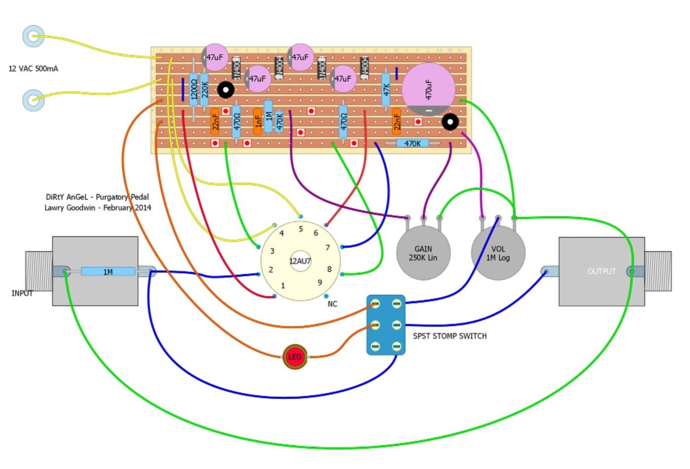
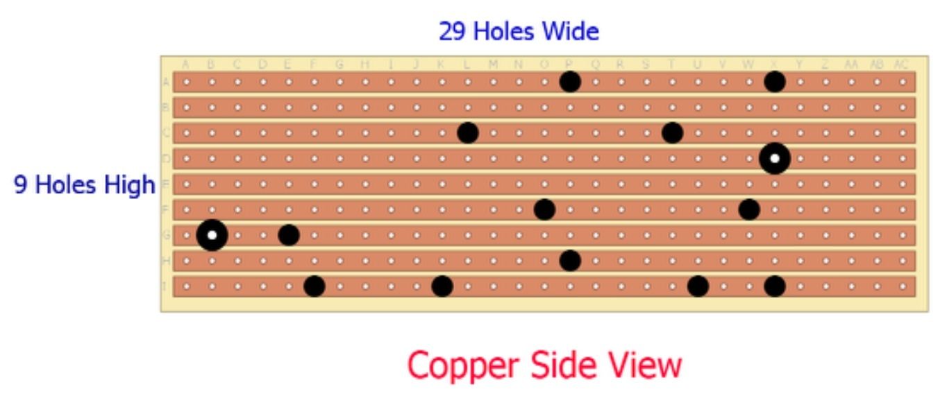
2) the layout drawing shows the components on the top of the board, not the copper side.
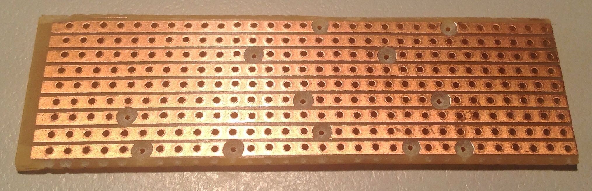
3) the copper side pic shows where you need to cut the tracks and where the two mounting holes are on mine.
4) firmly twist the power wires (and those that go to the valve heaters pins 4 & 5) to help reduce hum.
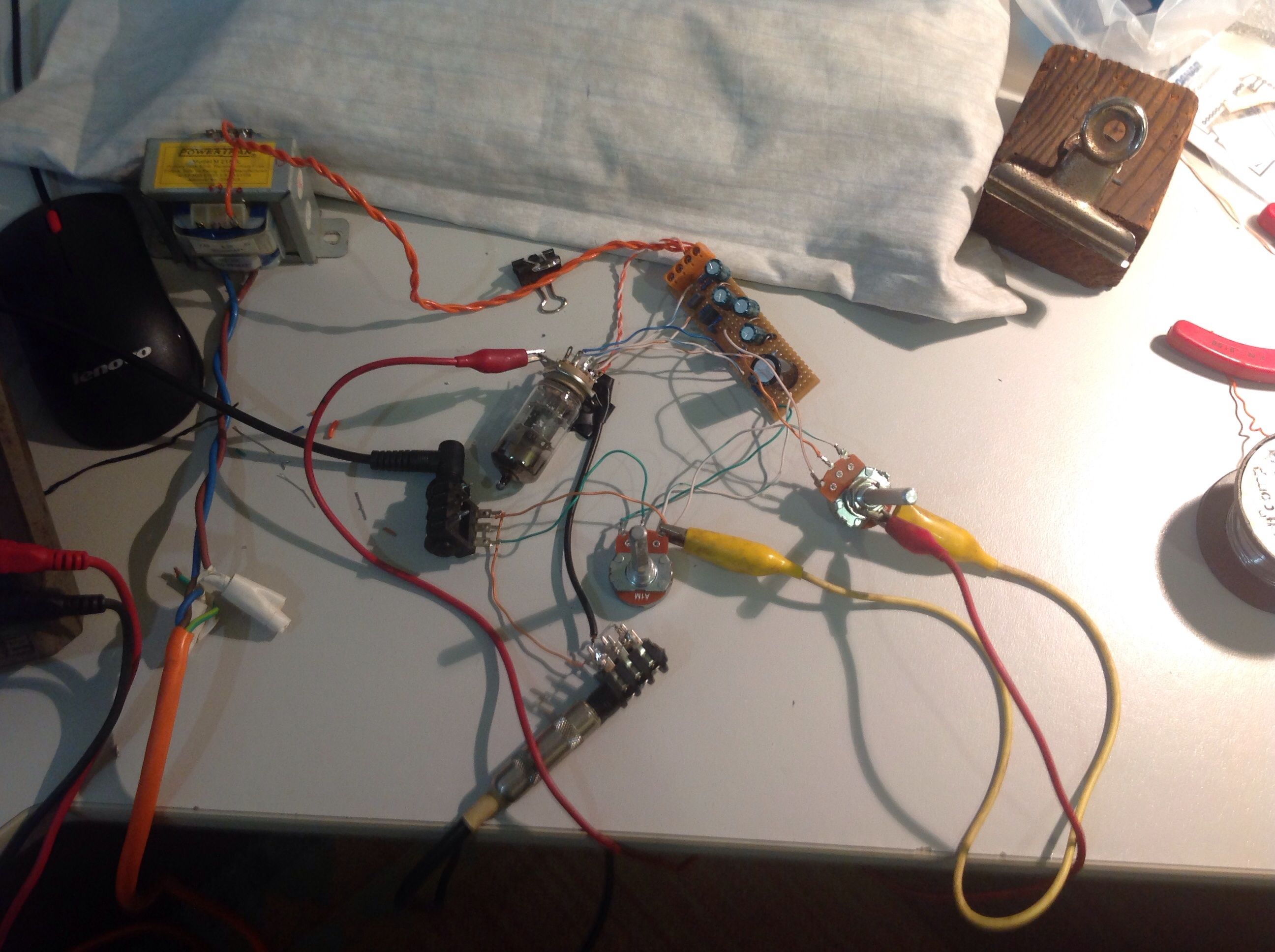
I have used a 12 volt transformer for testing but when I put it in a box I will use a 12 VAC plug pack. Also, I had not connected the foot switch or LED in the pics below. That will be done when I mount things in a box.
So, go for it...
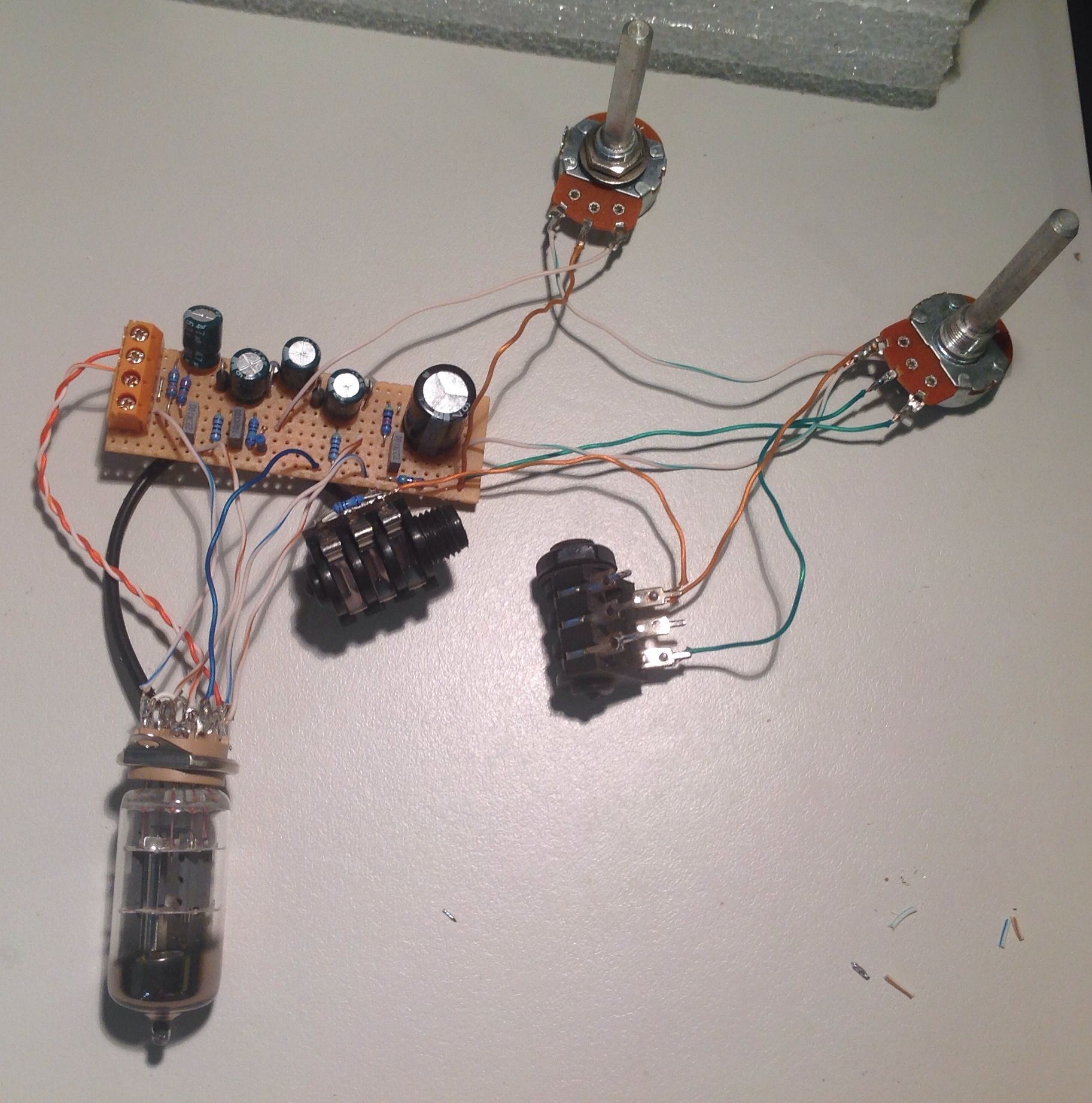
And here are some reality pics.
Copper side with tracks cut.
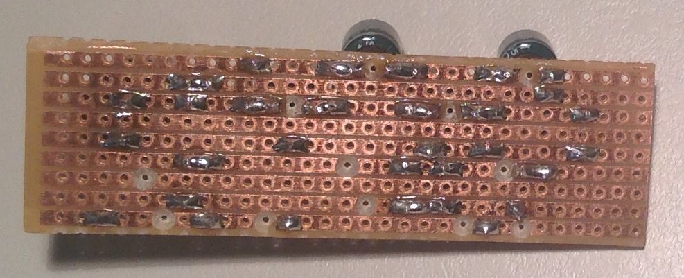
Copper side with components soldered in place.
Component side.

And finally, some assembled pics.
Just gotta buy a box and do the finishing off.
 Posting Permissions

 Reply With Quote