You want the flat edge to just rest on the neck,/frets, not touching the nut at all. You may now have taken too much height off the bridge, though if the string tension lifts the top up, then things may balance out.
9mm is probably far too thick if you are sticking the block under the bridge on the inside of the guitar. Think about how the strings are actually held in place by the bridge pins. The bridge pin pushes the ball end forwards, so that it is half-resting on the underside of the top. It's this that keeps the string in place, not friction from the bridge pin.
So you don't want the depth from the top of the saddle to the bottom of any bridge plate underneath the saddle to be too deep, otherwise the bridge pin won't be long enough to push the ball end forward and the string will keep pulling out. You ideally want that overall depth to be about the length of the twisted section of the string above the ball-end, so roughly 15mm. A bit deeper is OK, but probably no more than 20mm as you want the bridge pin to extend beyond the ball end.
You don't want it too shallow either, as you don't want the thick twisted end of the string to extend above the top of the bridge as it won't bend easily and so (especially on the wound strings) you'll end up with a much shallower break angle over the saddle. So 14-15mm is probably the shallowest overall depth you want.
You should be able to stick something through the hole and mark up on each end where it emerges to see what depth you currently have, and work out what the thickest base plate you can use is.
You can certainly make your own Bridge Doctor style support, but note that you really do need the ability to adjust the length under stress of the post running to the rear block, rather than having a fixed length that just rest against the back (which may also cause buzzing if the top lifts and pulls that post away from the block slightly).
It's the ability to screw in the thread that presses on the rear post that makes the Bridge Doctor work, so anything you do needs to have that ability, and you need to be able to adjust that from the sound hole.
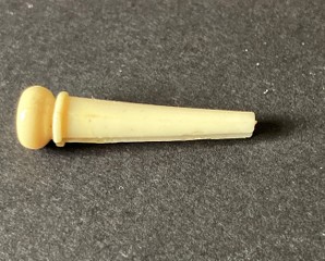
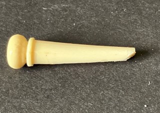
It's also a good idea to sand an angle onto the forward facing end of the bridge pins. This stops the ball-ends being caught so that they sit on the bottom of the bridge pin and not against the top. This either results in the bridge pin being pulled up by the string when you start tensioning the string, or the string slipping as it gets pulled off the end of the bridge pin once there is some tension applied.
The angle pushes the ball end forwards as it's inserted, so ensures it starts in the right position.
It takes seconds to do with a piece of sandpaper on a flat surface.
Thanks a lot simon for your constant useful inputs - i did have some suspicions about the pegs that the added thickness would give me problems, i havent finalized the install of anything yet, so there is still time to either reduce its entire thickness or use drillbit to increase the depth of the holes
Note ; Since i did remove a lot of material from the top of the tailpiece- the pins have dropped 6-7mm and i will be adding 10mm of total thickness, so it is more of a fine tuning
And yes it was poor placement of the straight edge but when i did string up two strings and they both held good action, so 10 more will certainly increase the action, here is a picture of when i test mounted low and high E and tuned them up
Oh yeah about the stewmac hardware, i loved the concept but i really want to do my own thing in that case, just want to get a heads up here if it appears reasonable, its a sketch and only displays what hardware it will interact with, so imagine it inside of the hollow
Those triangles mounted to the plate is just to move the point of rotation further away from the base and give more leverage
I hope it makes sense, to me it would be reasonable that you can mitigate most of the torque caused by the strings and thus put a stop to the bulging of the top, btw reckon steel wires under tension within the sound chamber of a guitar will affect it a lot?
What do you think? Is my plan waay over the top or am i gonna have greater success with the guitars stability in the future and not having to worry about string gauge and half steps up etc? and since its running 12 strings i reckon the problem is liable to reappear if not done right
For me, that would still be a high action, though I expect it might come down a bit with lower nut slots.
If the top stays as it is but just the neck bends, then that should be able to be straightened out by the truss rod. If the top is pulling up, then you need to do something to stop that.
Your idea is certainly working along the right lines, though I'm not quite sure just how you could tension the wires. I think the tips of your triangles, if made of wood, are going to be fairly weak and may be prone to breaking.
You may be able to rig up a Strat-style trem claw arrangement, with the wire attached to the claw and you can screw that into the neck black and adjust the tension via the screw, but even so, the practical access for screwdrivers and drills in the soundhole isn't easy. Looks OK in theory, but you can't grip things well once they are inside the guitar.
There is also the distinct possibility that the tension wires will vibrate and be audible when you play.
What about making a Bridge Doctor type wood block, but with a metal threaded insert and use a length of say M6 threaded rod (instead of the plastic rod and metal screw)? You could either slot the soundhole end of the rod so you can screw it against the rear block, or maybe glue/solder/weld a nut on the rod, so you can turn it with a spanner/socket wrench.
When i took the picture displaying action height, the bridge was set 3mm too high, not much but i need all i can get
Yes the triangles are made out of maple and my intentions are to cover the tips with some thin copper sheet
And yes you are right about the method of how to go about adding tension to the wires through the soundhole especially with 12 strings in the way, will be difficult, if i dont come up with a really elegant solution (because i am stubborn and its a fun learning process)
If all my plans fail ill take your advice on making a bridge doctor style block instead =)
I'm no expert on this, I'm only making (what I think are reasonable) suggestions, so please go ahead and do what you think reasonable.
I'd just suggest having a bit of a flat top to the triangles instead of the thin point.
You could always look at it that if you fail, you haven't lost anything. If you get it to work, you have a playable 12-string.
You should only have to set the tensioning up once. You can always slacken the strings off to get tools in the soundhole. I often put tape round the strings or use a capo up by the nut to keep the strings on the tuners and then slacken the strings off so I can remove the saddle to work on the height.
I'd also note that the bridge doctor has a screw at the back of the bridge to hold the block in place. That might be an idea, as it could be hard to hold the rear of your under-top block on firmly enough with glue as its not in the easiest position to clamp firmly and the action of the wire tension is to pull the rear away from the top.
I have some bridge clamps which would certainly do the job, but if you haven't already got any, they aren't that cheap unless you get them from China - and then you have a long wait for delivery.
Good points Simon and it got me thinking, if the 'underblock' was to fail due to the pulling forces you are referring to, thats a disaster.
It made me rethink my plans, to this
(Drawing not fully accurate, that little angled piece to the left should really be 10mm higher, visible, on the guitar top right behind the tailpiece)
I make a suitable piece out of walnut or maple, to fit nicely against the existing tailpiece, with a 45 degree back face on which i drill all the way through the body of the guitar and backplate, i will end up quite nicely in line with the "sharp triangles" on the backplate
I can then use some m6 machine screws with internal hex heads to run through and connect to the wire
I realise as it is drawn in the picture the wire is gonna spin with the bolt, but i have a plan to fix that
And the main point is of course to be able to adjust the tension without anything in the way!
Also to reduce much of the strain on the 'pulling' side of the backplate
I wonder if a curved - semi-circular or semi-elliptical (or at least with a rounded low point) - pivot block wouldn't be a more durable implementation of the idea ...
I made a support bracket out of maple to mount behind the bridge in order to counteract the belly-ing
I drilled through the soundboard and also found two copper ferrules that happened to fit perfectly
I stained the maple but i think it went way too dark, gotta do some sanding
This is how its gonna end up looking, the tension wire is going to loop around the support bracket and be visible but recessed into the maple
The dirty and scratched top is very distracting, any tips to get it looking a little better?


 Reply With Quote