Results 1 to 6 of 6

Thread: Strat - 3x SC, 2 tone, 1 vol, 5 way switch - Conflicting diagrams

  1. #1

    Strat - 3x SC, 2 tone, 1 vol, 5 way switch - Conflicting diagrams

    Once again, I'm lost in a world of wiring diagrams. I've got an AST kit which comes with a loaded pickguard.
    I'm wanting to do away with all the kit electronics and put in different gear. I've already got the pickups and I've order the pots and switch today. Because the kit comes pre-wired, the PB diagram doesn't show any of the stuff that's already wired, only the connections needed to complete the kit. So, looking around, all diagrams I find for this configuration don't match the way the kit has been pre-wired. Although, there is a wiring diagram for the JZ-6 which seems to match how my kit has been pre-wired. I just don't understand the significance of the differences.

    This seems to match how my kit was pre-wired - https://www.pitbullguitars.com/wp-co...ng-Diagram.pdf

    Both tone pots have caps (look like .047 but need to take a photo and zoom in to be sure). However, if I look at standard wiring diagrams for this configuration, including the Tonerider diagram - https://tonerider.com/wp-content/upl...v=6cc98ba2045f - they all show a cap on just one tone pot. Even the normal ST diagram for pre-wired pickguards shows one cap only - https://www.pitbullguitars.com/wp-co...0ST-1_2014.pdf

    The only other time I see diagrams with a cap on each tone is for HSS configurations.

    So, my question, is my pre-wired pickguard wrong or does it not really make a difference? Should I follow the Tonerider diagram when re-wiring? I never really understand what I'm looking at with wiring diagrams - it's a paint-by-numbers experience for me.

  2. #2
    GAStronomist Simon Barden's Avatar
    Join Date
    Oct 2016
    Location
    Reading, UK
    Posts
    10,547
    This is a good question, and it made me think (which is always good).

    Both setups work, and the difference is subtle and only affects the combined neck + middle sound, so it's a matter of personal choice.

    The Fender way is to have a single cap. This is really for historical reasons, from when Strats only had a 3-way switch. Ignoring the reasons why Leo didn't choose to fit another tone pot for the bridge, or use a common tone pot, you could use two pots with a common cap to give different tones. Also, a cap costs more than a piece of wire, and Leo certainly didn't spend on components that weren't needed (in his opinion).

    The sounds of the middle and neck pickups aren't too dissimilar, so the same cap value could happily be used for both pickups. When the neck pickup was selected, the middle tone pot was unconnected at one end, and so out of circuit. Likewise, when the middle pickup was selected, the neck tone pot was unconnected at one end, and so out of circuit.

    When they finally fitted a 5-way switch to make getting those position 2 + 4 tones easy, they kept the single cap arrangement.

    What this meant was that in position 4 (neck + middle), you ended up with the neck and middle tone pots both in circuit wired in parallel. This means that the effective pot resistance is reduced, so the sound immediately has a bit more treble rolled off.

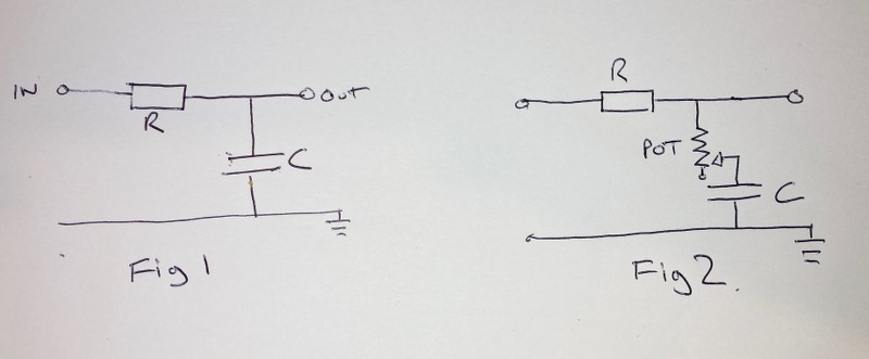
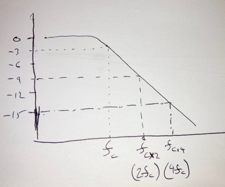
    A guitar tone circuit is a basic low-pass single stage 'RC' filter comprising a resistor and a capacitor arranged as in Fig.1. The values of the capacitor and the resistance determines the 'cut-off' frequency, below which frequencies pass to the output, and above which the frequencies are passed down to ground in increasing levels as the frequency increases. In the diagram below, Fc is the cut-off frequency. Fc is actually defined as the frequency at which the output is attenuated by 3dB, so you are are already rolling off frequencies at this point. (Mainly because it's easy to measure a 3dB drop in output, and very hard to measure exactly where the output starts to deviate from a straight line. Plus 3dB is the point where most people can hear a difference in the sound regardless of frequency or volume).


    (X axis = log frequency, Y = dB of attenuation)

    A basic first order low-pass filter has a 6dB/octave roll off, so that at double the cut-off frequency (one octave up), the attenuation has risen by 6dB to 9dB, and at four times the cut-off frequency (two octaves up), the attenuation has risen by another 6dB to 15dB etc.

    In a guitar or bass, the 'R' in the circuit can be taken as the pickup coil resistance, or rather impedance as it's a little bit more complicated than that as the pickup inductance and capacitance and the volume port resistance to ground are also involved. But as a rough approximation, take it as the pickup coil resistance.

    But whilst we like the ability to reduce the treble and mids at times, we generally don't want to loose those frequencies and keep things bright sounding, so we add in the tone pot, wired as a variable resistor, as in Fig.2. With the pot at full resistance, almost none of the current/voltage generated by the pickup flows down to the tone capacitor, so the output signal remains bright (not as bright as if the tone circuit wasn't there at all, which is why no-load pots with a break in the track to fully disconnect the tone cap exist).

    As the resistance is decreased, more and more of the higher frequency signal is passed through the capacitor, dulling the sound, until finally with the pot giving no resistance and the full higher frequency roll-off is achieved

    Note that the tone pot resistance is not the 'R' in the RC circuit, it is there just to vary the amount of high frequencies that pass to ground.

    If both tone pots were up full, you'd normally expect 250k resistance if a single pickup was selected. But in that position 4, with the neck and middle pickup selected, both pots are in circuit and in parallel, so the effective resistance is much less. With both pots at maximum resistance, you get 125k, not 250k. Which is like turning a linear tone pot down to 5. In reality, this doesn't have a huge effect, and you may not notice it at all on a single pickup, but in position 4, which is a bright 'quacky' sound due to lots of phase cancellations and boosts from mixing the two pickup signals, there is the effect of mellowing the sound a bit, and helping to differentiate it from the position 2 (middle+neck) sound.

    Obviously if one or both tone pots are turned down a bit, the overall effect is greater.

    If each tone pot has its own capacitor, then you don't get the resistances in parallel situation, but you do now get both tone caps in parallel, which effectively doubles the tone circuit capacitance value (0.094uF rather than 0.047uF) and so lowers the circuit cut-off frequency. If both tone pots were rolled right off, then the sound would be much muddier, but with the tone puts up fully with maximum resistance, you'd hardly notice a difference as each tone pot circuit the acts more like an individual circuit.

    The end result is that with the tone controls both on 10, on a single tone capacitor system, the position 4 sound has slightly less treble than a double tone capacitor system, resulting in a bit more of a difference in sound between positions 2 and 4. With both tone controls on 0, the single tone capacitor system will be a bit less dull and muddy than the double tone capacitor system, but that's a very unlikely playing scenario.

    Why do the kits have two tone caps? I'd hazard a guess that its easier for the factory making the loaded scratchplates to have one trainee soldering caps to pots, and another to do the wire soldering, than to give someone the responsibility of doing both. But i have no real idea.

    Obviously using two caps means you can tune your tone circuit per pickup, and some pickup manufacturers e.g. Lindy Fralin, go the two different cap route on their wiring diagrams.


    To sum up:

    1. Both circuits work well.
    2. The sound is only slightly affected in the neck + middle pickup position
    3. Two caps will make the neck + middle pickup position very slightly brighter than a one cap circuit with both tone controls on 10.
    4. Don't worry about it.

  3. #3
    Overlord of Music McCreed's Avatar
    Join Date
    Oct 2018
    Location
    AUS
    Posts
    3,552
    As usual Mr. Barden is all over it, and with way more flair, detail and enthusiasm than I am capable of!
    FWIW, I began replying hours ago but got pulled away...
    So this is all I got, which may or may not help

    Like most things guitar, there are many ways to skin the proverbial cat.
    The single cap or dual cap wiring is a matter of personal preference. In very basic terms, you can have two different value caps for each pot to effect the corresponding pickup differently. A single cap scheme "shares" the cap between the two pots.

    If you're essentially starting from scratch with new pots and switch, I would forget about what PBG has done and find a diagram that will give you what you want. I prefer to wire the bridge pickup into the tone circuit as I think that's the pickup that really needs a tone control the most, but that's just me.

    Again there is more than one way to accomplish these or a standard strat wiring, but here's 3 takes on it:
    (in very much paint-by-numbers format)

    Dual Cap Strat:

    Click image for larger version. 

Name:	Dual Cap Strat.jpg 
Views:	83 
Size:	80.2 KB 
ID:	41933

    Single Cap Strat (traditional):

    Click image for larger version. 

Name:	Std Strat Wiring.jpg 
Views:	89 
Size:	123.3 KB 
ID:	41934

    Single Cap with Bridge p/u added to Tone Pot 2:

    Click image for larger version. 

Name:	Strat Bridge Tone Mod.jpg 
Views:	86 
Size:	121.5 KB 
ID:	41935
    You'll notice the only difference between the "standard" and the "bridge tone mod" is the addition of a little jumper wire on the switch between the two middle lugs on the "tone side" (aka stage 2) of the switch. (turquoise wire in drawing)


    Pardon the screen grabs, I've lost my original drawings
    Making the world a better place; one guitar at a time...

  4. #4
    Wow! I thought I had a decent understanding of electronics. Obviously by no means an expert, but I did pass a variety of analogue and digital electronics subjects in TAFE (admittedly that was MANY years ago). I even had to build a 0-30V, 5A variable power supply to the point of starting with designing the circuit, etching the board, building the case from scratch (I still have it and it still works).

    But whenever I start reading Simon's electronics explanations, I feel like a complete dunce. I need to find some resource material that's specific to guitar circuits so I can get a better understanding of what it all does. I'm pretty sure you covered a lot of it above, and I thank you humbly for your detailed input, both of you. I never realised until these past couple of years just how many options there are to wire up the same guitar.

    Thank you, thank you, and thank you. Now watch me still stuff it up. :-D

  5. #5
    Overlord of Music fender3x's Avatar
    Join Date
    Jan 2016
    Location
    Miami, FL, USA
    Posts
    2,200
    Ha! Well some of us start at a point well behind those who've gotten it in TAFE. I personally had to look up what TAFE is.

    The lovely thing about Simon's and McCreed's explanations is that they help to understand what the components do. They are also in writing, so that you can read them over several times, until they start to make sense.

    That said, one of the beauties of DIY is you can try it all three ways and see what you like best. It can be equally enlightening to try a few combos to see what's best to your ear.

    FWIW, if I had to pick one and could not test, I'd do it similarly to McCreed's slight mod. I don't have a Strat but I like being able to roll off the treble a little on the bridge pup of a Tele, and I am guessing I'd feel the same way about a Strat ;-)

  6. #6
    Overlord of Music McCreed's Avatar
    Join Date
    Oct 2018
    Location
    AUS
    Posts
    3,552
    But whenever I start reading Simon's electronics explanations, I feel like a complete dunce.
    Don't worry you're not alone!
    My understanding of electronic theory is tenuous at best. TBH I hadn't even thought about the "how's and why's" of two caps affecting the overall circuit. Just how they rudimentally relate to the individual pickup positions.

    I missed failing Electronics in high school by the skin of my teeth. I wish I'd paid more attention now... and probably should have turned up more often too .
    Last edited by McCreed; 21-10-2021 at 06:47 AM.
    Making the world a better place; one guitar at a time...

Posting Permissions

  • You may not post new threads
  • You may not post replies
  • You may not post attachments
  • You may not edit your posts
  •