Page 2 of 8 FirstFirst 1 2 3 4 ... LastLast
Results 11 to 20 of 73

Thread: GST-1 'Hexacaster' build

  1. #11
    GAStronomist Simon Barden's Avatar
    Join Date
    Oct 2016
    Location
    Reading, UK
    Posts
    10,547
    It's been sunny and warm enough to work out side for the past three days, so I've been doing a lot of initial work on the kit.

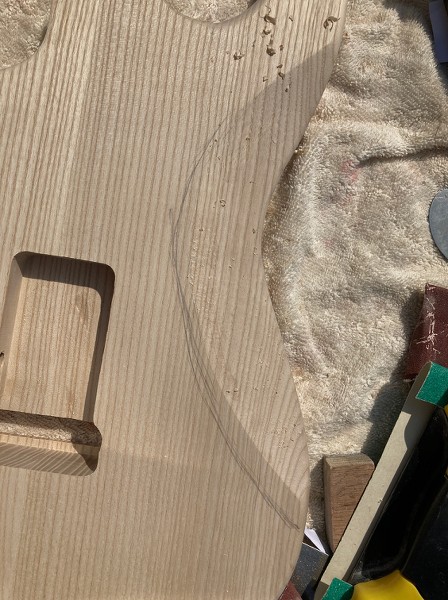
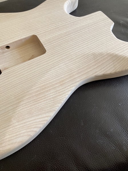
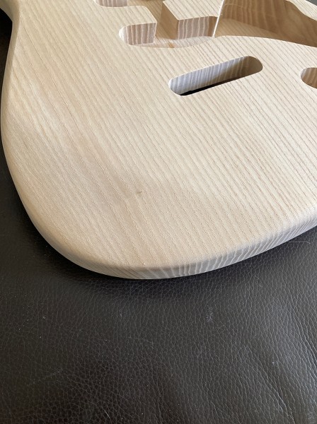
    Both the forearm cut and the belly cut are smaller than on a real Strat, so they've both been enlarged to match the general size and shape of my Dave Gilmour Strat. I know that these exact dimensions will have varied over the years, and even from guitar to guitar in the first decades of production because of the hand sanding, but you need to pick some reference point. The belly cut was fairly close and mainly needed lengthening, but it also got slightly deepened. Before:


    After:


    The forearm cut was fairly minimal and much too short, running down to just 1/4 of the body height, so it now extends down to 1/2 way and is gently 'rolled over', rather than being very angular and meeting the top with a very defined line.


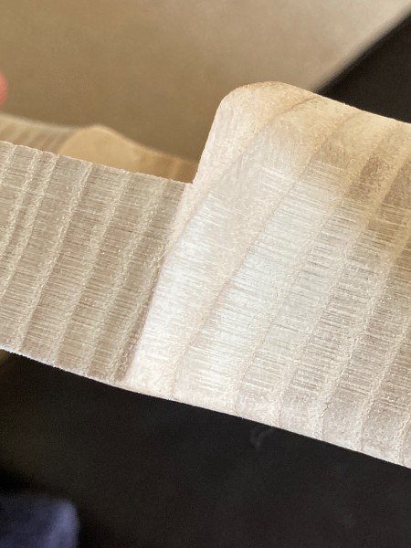
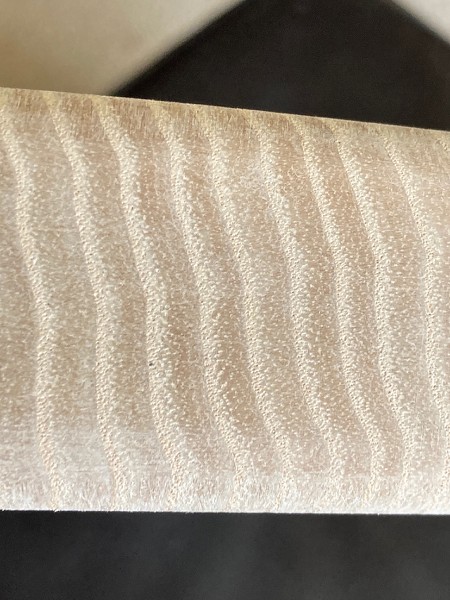
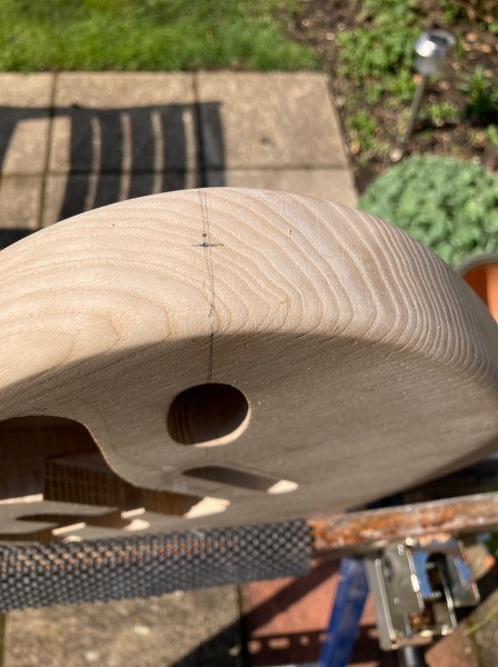
    There's been a lot of sanding to do. The factory obviously use a fixed drum sander, rather than an oscillating one, which has left very definite parallel score lines all around the body edge.


    It's taken the best part of two days to get rid of these. Didn't have anything coarser than 80 grit paper, but could have done with some P60. I could do a lot of the convex curves with a random orbital sander, but all the concave ones and within the horns was all manual sanding. At least there's nothing to show up under the lacquer now.


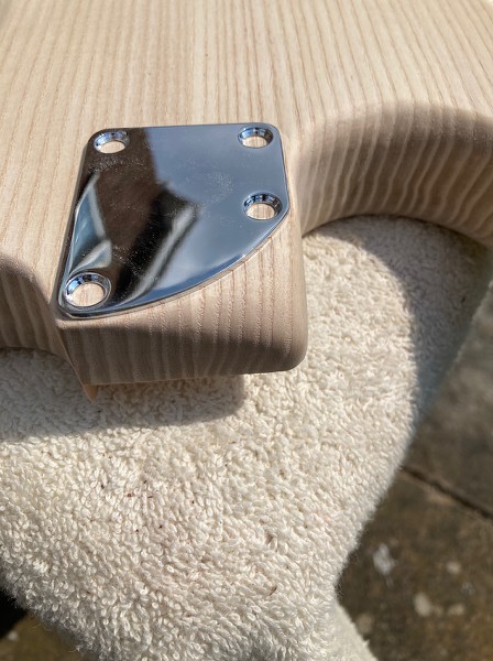
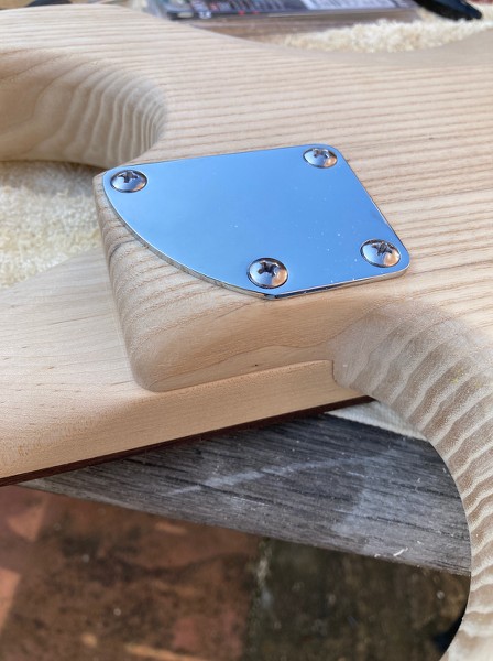
    The rounded heel plate arrived yesterday, so I rounded over the lower heel edge in what (I think) is a similar manner
    to the latest Fender USA contemporary style.


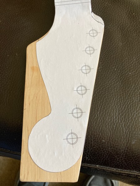
    The headstock was cut to give a certain classic look. Paper template first stuck on:


    The kit necks have a rather elongated section between the nut and the 'flared out' section of the headstock, so the tuners will always be further away from the nut than on their inspiration.

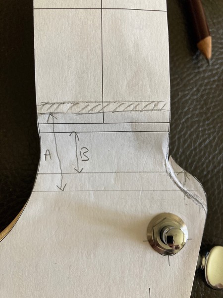
    Here's a close-up of the nut area of the headstock. I've shaded in where the kit nut is, and you can see where the template thinks the nut should be. Because the bass side curves of the template and actual headstock are different' it's not easy to say exactly how much the neck is stretched in this area, but I drew lines to roughly the same relative points on the curves, and measured from the respective nut positions, and A (kit) is 27mm, B (vintage) is 14mm. So a 13mm stretch.


    Obviously the positioning of the template is dictated by the main headstock outline. The headstock holes are slightly further apart than on a vintage headstock, so fitting vintage tuners (that need to butt up against one another as they share a common mounting screw) isn't an option here, at least not without plugging the holes and redrilling. So I positioned the template so that the high E tuner hole corresponded with the high E template hole in order to keep the scroll end of the headstock as near the nut as possible. The headstock is already stretched out compared to the original, so there was no point using the low E tuner as the reference point and moving the scroll end another 3mm or so away from the nut.

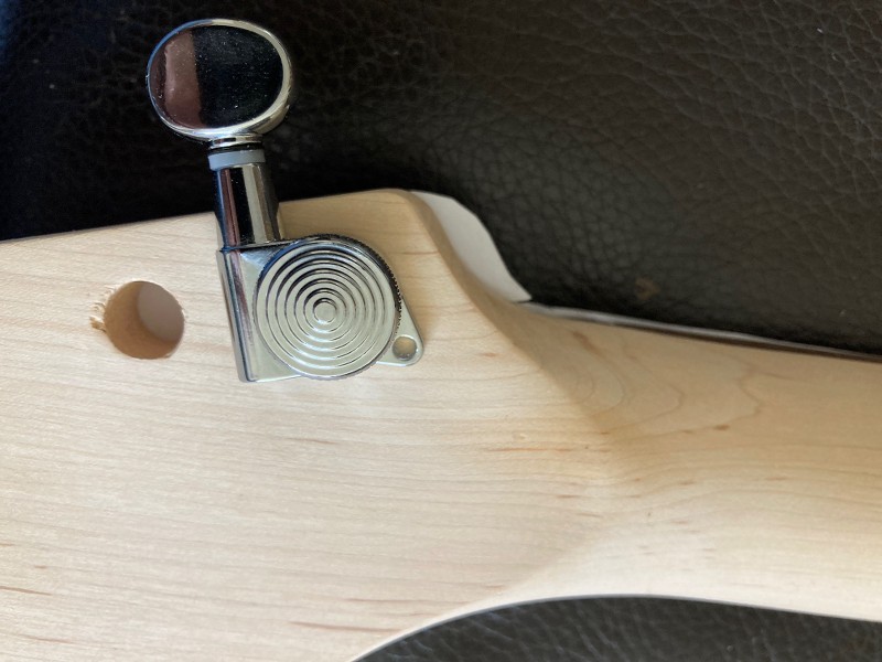
    Luckily I wasn't planning to fit vintage-style tuners, so I fitted a tuner (NorthWest Guitars locking style) to make sure there was sufficient gap between the tuner and the end of the headstock, but this was fine.


    On my EX-1 kit, the low E tuner sits right against the edge of the headstock.

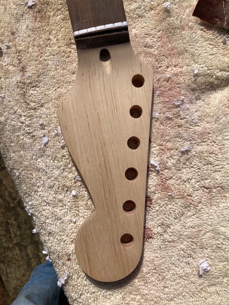
    Edit: Forgot to add the rough cut-out headstock picture. I did a bit more more sanding after this, especially on the nut/fingerboard join area to get that looking straighter. It was all a bit wonky straight from the factory, which spoils the look:


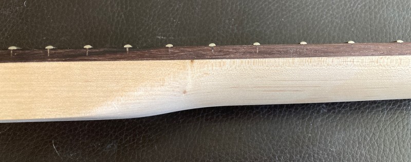
    I also smoothed off the neck's heel so that it flowed into the heel join area, without the large flat area that normally pokes out a couple of cm on this style of neck.


    When the neck is put on the guitar, the combination of the two lots of heel roundings gives a much more natural heel to moving your hand up the dusty end, with no impediment to upper fret access.

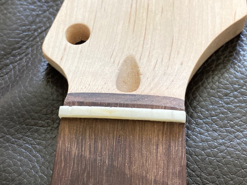
    I removed the nut to replace it with a bone one, but all my pre-shaped nuts were too low, as the nut slot on the guitar is quite deep. The old nut wasn't glued-in very well, there was a gap between it and the bottom of the sot on the bass side, and it only took one light tap to free it. So I cut a nut from an acoustic saddle blank I had, using the old one as a template. No point in finessing the shape now, as that will get done in the final set up,


    I've had to fix cracks and small faults in the body, which I'm not happy about. Some were tear outs from drilling (dull bits) and router tear-outs (routed edges seem clean so the router bits seem to have been pretty sharp). But also what now seems to be the norm of the usual body piece glue line splits. There was a 2cm one on the underside of the end of the body, and a much longer one running down the trem cavity area, with light showing right through. There was also a crack to the side of the centre line.


    I've filled the cracks with superglue and will need to sand off the excess glue today, after leaving it to dry overnight. The body is being sprayed with a translucent green, so I've no problem with dye not being absorbed by the CA. But others making the same guitar could suffer.

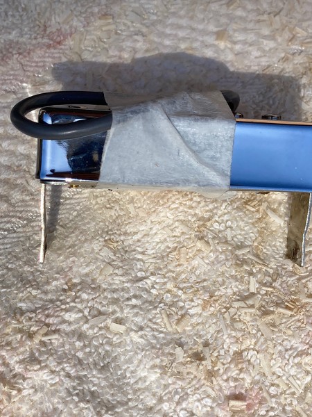
    After doing all that, I rubbed off the gold plating on the pole screws on the bridge Gibson 500T, and then fitted a metal cover it. Not forgetting to melt wax in the top of the cover first before soldering it on and then heating it up again in order to stop any microphonics from the cover. I was going to take pics of the process, but I forgot.

    I now need to do some routing, initially so I can fit the humbucker in, but my palm router has gone missing. So I'm awaiting delivery of a new one before I can do too much more.

    I'll need to drill, rout and chisel a cavity to fit the GK 13-pin connector in, and then try and work out how I can fit the GK board inside the control cavity and still keep the two planned push/pull pots. I'll probably have to rout the bottom of the cavity lower (it's 10mm thick at the moment, so I've got a good 5mm to play with), but the push-on connectors are all vertical and spaced around the edge so need some decent height above to fit in. But I'm hoping that I can arrange the board so the switched pot sits in the centre. Otherwise the switched pot will have to go to reclaim the necessary height.

    And I just realised that I'd left some electronics items sitting in a basket rather than checking out, which is why they haven't arrived in the post. D'oh! So just sorted that out.

  2. Liked by: Tadhg

  3. #12
    Mentor dozymuppet's Avatar
    Join Date
    Jun 2020
    Location
    Perth, WA
    Posts
    842
    Epic update. Thanks Simon

    Sent from my Pixel 4 using Tapatalk

  4. #13
    GAStronomist Simon Barden's Avatar
    Join Date
    Oct 2016
    Location
    Reading, UK
    Posts
    10,547
    Some more general comments on the SGT-1 kit as a non-modified kit:

    The hardware supplied with the kit - scratchplate and trem, coupled with things like overall neck length, do make it very hard to assemble the kit without at least some basic modifications. I've been having a discussion with Tadgh, whose also got a GST-1 kit, over his issues, and mine would be quite similar.

    If you built the kit as it came, and left a slight gap between the front edge of the trem plate and the kit pickguard you really couldn't intonate it. Butting the plate up to the pickguard (which inhibits trem movement), you can just move the high E string saddle forwards to the 25.5" position, with about 1mm of thread in the saddle block. I wouldn't want to have my saddles held on by that little screw length.

    There are a three main issues at play here: 1) neck length, 2) trem plate length and 3) pickguard length.

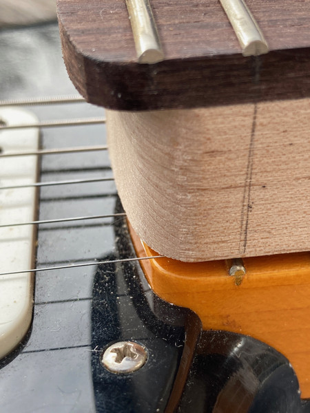
    1) The neck on my GST-1 is about 1-1.5mm longer than my Fender Strat neck length. I'm not talking about scale length, that's fine, but the length of the neck from the nut to the heel end of the neck. Comparing the kit neck length against the DG Strat (and you'd expect Fender's custom shop to get it correct), you can see it's just that little bit longer.


    The fact that it's a 22 fret neck doesn't particularly matter here, though the factory have probably made the neck a little bit longer to provide more support for the 22 fret overhang.

    Remember that that 1-1.5mm moves the nut that bit further away from the bridge position, meaning the saddles have to move forwards by the same amount.

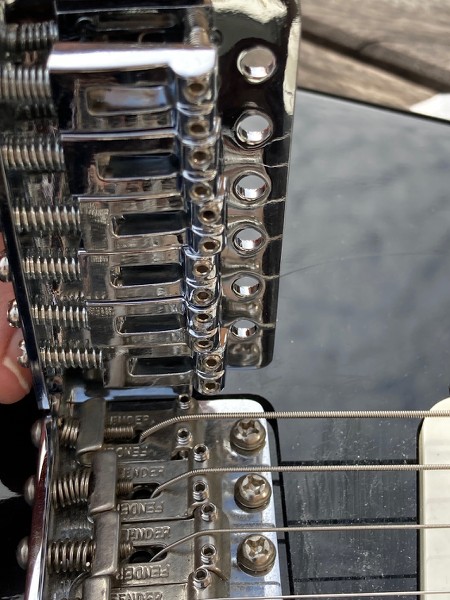
    2) The kit trem plate is about 2mm longer from the front side of the folded-up metal rear at the back of the trem to the from of the trem plate than standard Fender vintage style trem.


    On its own this wouldn't matter if the saddles could be moved forwards sufficiently to counter the extra length, but they can't as supplied. When wound forward as far as they can go with some thread still in the saddle block, the kit saddles have about 2mm less forward movement than the Fender bent steel saddles. Which means as the kit saddles start 2mm further back than the Fender ones, there's 4mm total less forward movement on the kit saddles than on the Fender (or a drop-in replacement like a Wilkinson).

    3) The length of my kit scratch plate (from trem plate-cut to the inner apex of the neck cut-out ) is about 165mm. Tadgh's (which he got 6 months before mine arrived) is a bit longer at 169mm (which is the same length as my DG Strat. Maybe the factory switched supplier of the loaded plates, I don't know. But the outcome is, that on my kit (100% factory version), getting the intonation length right is just about possible, on Tadgh's kit it isn't.

    The longer trem plate and its pushed-back position mean that the trem block now sits nearer the rear of the trem block cavity, so you can't depress the trem far before the block hits the back of the cavity. I know it's not a Floyd Rose, but you should still be able to get a reasonable amount of trem action.

    It should be noted that Tadgh is fitting a Babicz trem, not the kit one, but some of these issues still affect his build. he's filled in the end of his neck pocket (which incidentally is at 80mm, 3.8mm longer than the Fender standard 3"/76.2mm pocket length) to allow him to move his trem forwards.

    Thoughts

    It's hard to make recommendations on a kit where each batch that arrives could come with slightly different components. But if you aren't planning to modify the kit at all and build-as is, the very minimum you really should do is fit longer saddle intonation adjustment screws. The standard kit ones are only 15mm long, so fitting 20mm long (M3 IIRC) intonation screws will give you a lot more adjustment. The kit saddles are made from ridiculously light alloy, so I wouldn't trust them to last long with only a mm or so of screw thread in them.

    Obviously there's a limit as to how far forwards you can screw the saddles as they will ultimately hit the trem plate mounting screws at the front of the trem plate, so 25mm screws will be too long. You may only need to fit longer screws on the G, B and high E saddles, as the others should intonate a bit further back. You should really have at least a couple of threads showing through once screwed in. If you get that on some saddles with the kit screws, then keep those, and just replace those where the screw sits within the saddle body.

    However, given that the trem block is also a cheap alloy unit, I'd give strong thoughts to replacing the kit trem with a Wilkinson unit with a steel block. This will give you a shorter trem plate, longer saddles and screws, more intonation adjustment and what should be a small improvement on sound and sustain from the steel trem block.

    You may also need to modify the scratchplate, to increase the depth of the trem block cut-out, allowing the trem plate to be moved nearer the bridge. This will reduce the need for the saddles to sit so far forwards and allow for more downwards trem movement.

  5. Liked by: Tadhg

  6. #14
    GAStronomist Simon Barden's Avatar
    Join Date
    Oct 2016
    Location
    Reading, UK
    Posts
    10,547
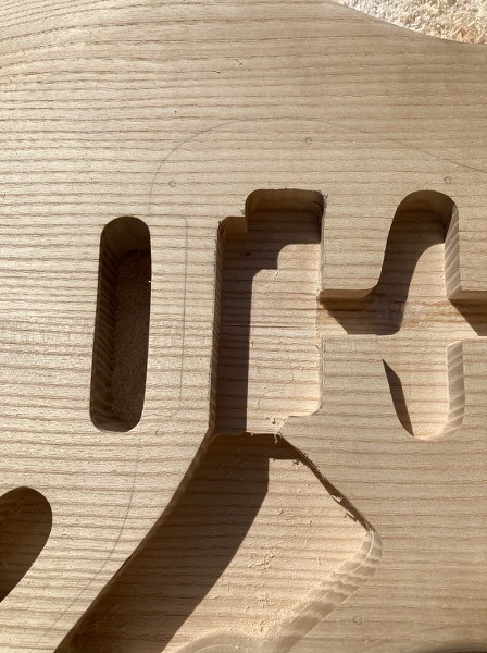
    The new palm router arrived, so I got straight into the process of enlarging the bridge pickup rout for a humbucker. And here we go (though it actually got enlarged a bit more since then as the bridge pickup fills the cavity and the pickup wires needed space to pass by:


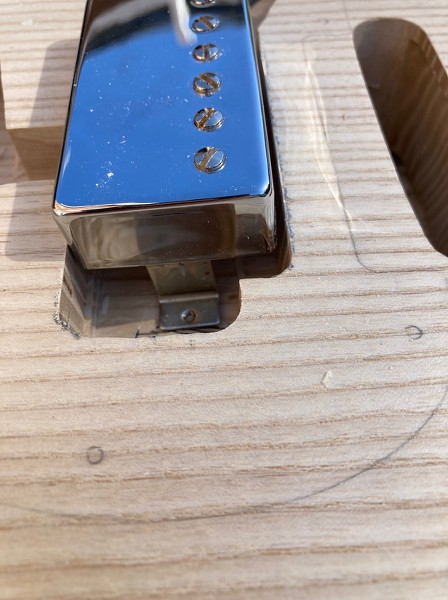
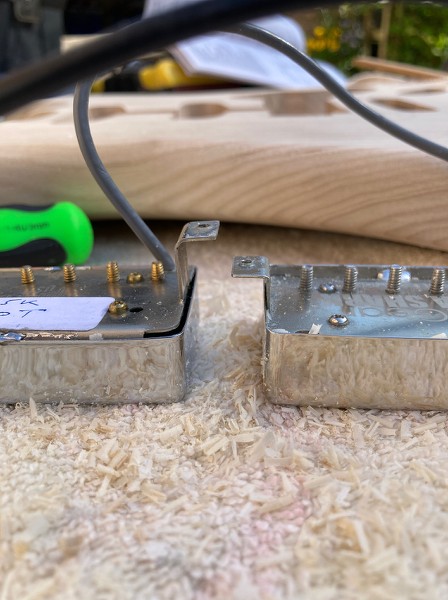
    But when I tried to fit the loaded scratchplate onto the body, it became apparent that there was a problem. Some pickups have short legs, and some pickups have long legs. The Gibson 500T had long legs and it wouldn't fit in the cavity without the pickup being far too high above the body:


    I had a short-legged pickup handy for comparison:


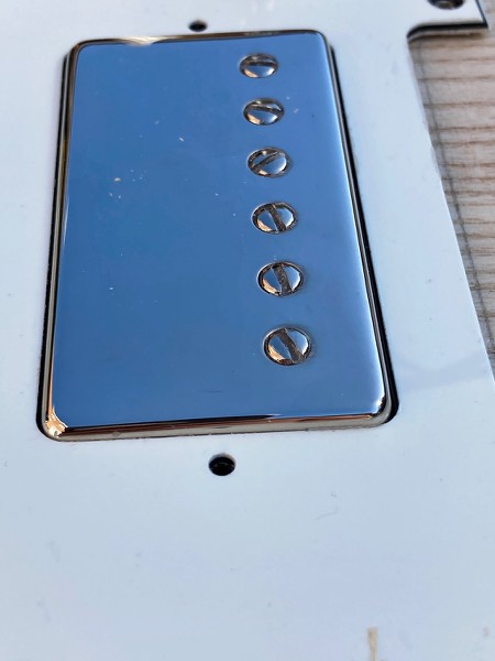
    And when I fitted that in the cavity and poked it through the scratchplate, it only just poked out, so something with similar, or shorter, length legs similar would be fine if fitted in the guitar:


    The alternative was to rout out the deep pockets you often get on the ends of humbucker routs just for long legged pickups, because with the trem cavity right behind the rout, behind it, the holes would go straight through to that.

    So, making the long legs short was the only real option. Time to first bend the legs straight, then bend them back over near the body, then drill a couple of holes and tap them out. I certainly got as far as straightening the legs:


    I've since bent them over but am now waiting to do the holes and tapping. Though I have various pickup height adjustment screws in various boxes, I don't know the thread sizes and I've only got got metric taps. So I'm awaiting a delivery of M3 machine screws tomorrow, as I know I've got an M3 tap and M3 is about the right size.

    I'm now packing up for the day, as I'm feeling tired, and it's stupid to do this sort of stuff when tired and more likely to make mistakes.

  7. #15
    GAStronomist Simon Barden's Avatar
    Join Date
    Oct 2016
    Location
    Reading, UK
    Posts
    10,547
    It was all going so well at first today.

    I’ drilled the neck screw holes, fitted the neck, and everything was aligning nicely and running down the centreline of the guitar. I found that the neck heel needs a bit of work to increase the neck angle very slightly, as the trem will need to be too close to the body to get a low action. I can always shim it if necessary, but I prefer not to for a new build.


    Then I started looking at the trem position and realised that the factory had routed the rear trem string and block pocket a bit off-centre. It also hadn’t been routed to full depth at one end. Which was just about OK for the kit trem but the Wilkinson trem I'm using has a block that is about 3mm wider overall, and couldn’t quite move sideways enough to centre the trem plate.

    So out comes Mr Router, and does a nice job of finishing off the rout and also extending it back a bit to allow more forward trem movement. The Wilkinson block is also thicker front-to-back than the kit block, so was hitting the rear too soon. Here I've marked on the area of wood to remove, after already removing the offending bit of wood at the side of the trem block rout:


    Mr Router then did a really nice job of deepening the controls pocket by 3mm to give a bit more headroom and room for wires. With the GK control board to fit in, any extra space helps.

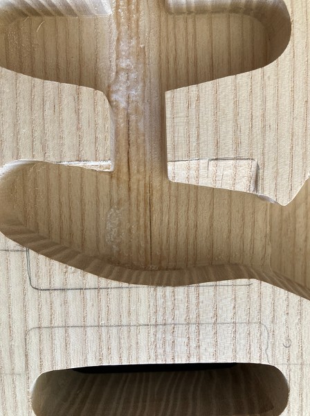
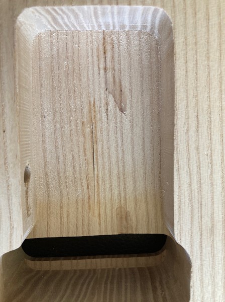
    I thought I’d then tidy up the floor of the humbucker rout and take 1mm off to again give a bit more room for cables. Except that the thickness of the wood between the floor and the trem rout was just less than 1mm. Holes appeared where there shouldn’t be holes.

    Surprisingly I only said one very quiet expletive.


    and on the back...


    At least you can also see the nice neat trem block rout extension as some compensation.

    I already have instigated my repair plan. I’ve glued some almost matching veneer on the bottom of the trem cavity, and that's sitting clamped up until tomorrow.

    Tomorrow I’ll cut some more veneer to roughly fit in the holes that will be left in the humbucker rout, and fix them in place with a UV setting resin (that will also fill in the gaps around the veneer) and then I’ll rout the surface of that flat - being very careful this time not to go deeper then the existing rout depth! I'll be reliant on the resin being delivered tomorrow before the sun drops too much, but the forecast is for blue skies for the next couple of days at least, so Monday if not on Sunday.

    Hopefully once the shielding tape goes in the cavities, no one will know it ever happened (unless they read about it here).

  8. #16
    Overlord of Music McCreed's Avatar
    Join Date
    Oct 2018
    Location
    AUS
    Posts
    3,552
    Looking good Simon.

    I thought I’d then tidy up the floor of the humbucker rout and take 1mm off to again give a bit more room for cables. Except that the thickness of the wood between the floor and the trem rout was just less than 1mm. Holes appeared where there shouldn’t be holes.
    I came very close to this recently deepening some routes on a previous strat build (I can't even remember which one now ) but I ended up with the existing wood very thin where the front and back cavities over lap. I left as it was since I didn't actually go through to the other cavity, but I'm sure if I poked it hard enough with my finger it would!
    I guess it doesn't matter structurally or sonically, but it bothered me just the same. I hadn't thought about veneering vibrato cavity side! Maybe next time it's on the bench for something else, I'll add that to the list... if I can just remember which guitar it was...

    Edit to add:
    Hopefully once the shielding tape goes in the cavities, no one will know it ever happened (unless they read about it here).
    Hah! Just read that bit and reminded me that I re-shielded the cavity too, and thought the same thing! Out of sight, out of mind!
    Last edited by McCreed; 25-04-2021 at 07:09 AM.
    Making the world a better place; one guitar at a time...

  9. #17
    Member
    Join Date
    Mar 2016
    Location
    Wyndham Vale
    Posts
    129
    I had the same problem with a set of pickups being too long but seeing as the material on the pickups are quite thin you really are not going to get enough threads to give an adequate thread strength, probably only about full 1 thread. I know they don't hold tonnage but you do need something that isn't going to strip or bind and give you grief. If you notice they actually extrude the material to give it a little bit more to tap but seeing as you probably don't have the tools to perform such feats here is what I did. You have access to a soldering iron and probably have some M3 nuts lying around, I used brass nuts to make it a little bit easier and what I did was solder a nut on the rear of the material and problem solved. You place the nut on the under side of the pickup as all the force is pushing and doesn't put any undue force on your solder. You said you have a set of taps so if any solder should enter the nut you can carefully clean it out. I used a wooden satay stick to align the nut and hole and I knew the solder wouldn't adhere to it and cause problems.
    Builds :
    # 1 - Non PBG ES-335
    # 2 - Non PBG Tele Thin line
    # 3 - Non PBG LP
    # 4 - Non PBG SG
    # 5 - RC-1
    # 6 - TL-1
    # 7 - ST-1 Custom
    # 8 - SGB-30 + Non PBG SG
    # 9 - Custom JRM-1DC 12 String
    #10 - Custom ST-1 with P90's
    #11 - Custom TL-1 with 27" Bari Neck
    #12 - Custom JZ-6 Jazzmaster
    #13 - AG-1 Factory Second
    #14 - Custom JZ-6 Bass vi
    #15 - EX-1R Factory Second
    #16 - AGM-1
    #17 - EXA-7

  10. #18
    GAStronomist Simon Barden's Avatar
    Join Date
    Oct 2016
    Location
    Reading, UK
    Posts
    10,547
    Well it tapped cleanly, the adjustment screw screwed in nicely and it's easily adjustable, so I'll leave it like it is for now. The pickup will need to sit quite low, and I'm not sure if there's enough room in the cavity to solder a nut underneath (not without filing it down to about half-height). If something goes wrong in the future, I always have that option. The act of tapping the hole did extend the metal downwards a bit, so there's probably a couple of threads depth in each hole.

  11. #19
    GAStronomist Simon Barden's Avatar
    Join Date
    Oct 2016
    Location
    Reading, UK
    Posts
    10,547
    Following on from last time, the veneer was stuck in the bottom of the trem cavity and left to dry overnight. The UV resin was poured into the holes (after first putting a few bits of veneer in the 'slots' to help bulk it out so it wasn't all resin) and taken outside to set in seconds in the sunlight.


    I then levelled the top of the resin with the router after carefully checking the router depth twice to make sure I didn't repeat my earlier mistake.

    The weather was has been quite cold and wet for the past week, so apart from working out how I was going to fit the GK board and still keep both switched pots (I can do it), I didn't do any more until today, when I created the hole for the 13-pin GK socket to sit in.

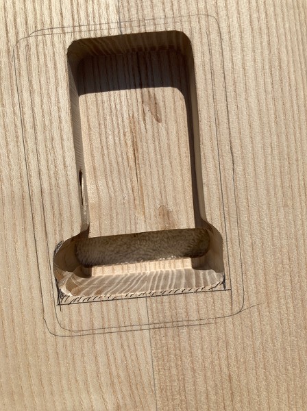
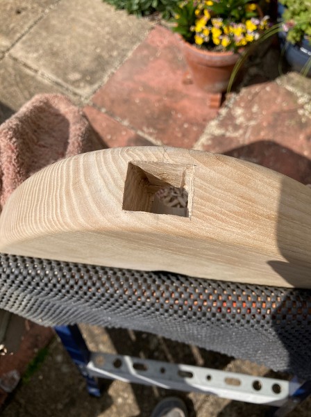
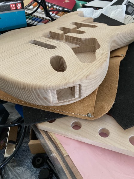
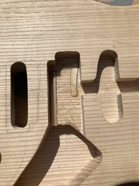
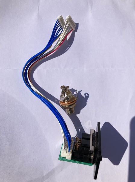
    As you can see, the 13-pin socket is a lot bulkier than standard jack socket, and necessitates the hole being rectangular. As I was all out of rectangular drill bits, I decided to drill out as large a hole as I could, and then enlarge it with a chisel. Yes, I could have tried doing it all with a router, but it would require a reasonably complex jig to support the router above the curved edge of the guitar and whilst I'm getting happier using routers, I'm still not very good at making templates, let alone a template plus a jig.


    The socket position was selected so that it's sitting underneath and joining up with the jack socket rout beneath the surface, making it relatively easy to get the two cables and their headers from that rout into the main control cavity. The only other position it really could have gone was on the underside and straight into the control cavity. But, the connector would then be in an awkward looking position on the side of the bottom curve of the body, and you couldn't sit down to play it on your knee in synth mode.

    So I marked out the centre of the body depth, in a rough line with the jack plate. I then checked the GK socket when fitted on its mounting plate, and realised that it sat offset on the plate, so I then moved my drill hole centre by 3mm (phew!).


    A 22mm forstner bit was used to drill the main hole. I needed a final hole that was roughly 22mm x 28mm, so I drilled out the corner locations with a 4mm bit and then set to with my trusty chisel to remove the remainder of the wood. And in no time (well about 2 hours in all), I had a deep rectangular hole.


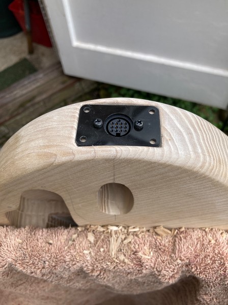
    I then needed to cut out a rebate for the mounting plate to sit in. In theory, the plastic mounting plate is flexible enough to simply sit on top of the curved edge. But posts in the VG Guitar forum seemed to indicate that this could cause intermittent connection issues with the 13-pin connector, so flat it would be. And in mere moments (maybe another two hours), I had a rebate for the plate.


    It then took little while longer to finesse the depth and get it as level as I could, but eventually the socket and plate fitted.


    I couldn't quite match the corners of the rebate with the rounded corners of the plate, so I'll either paint the bottom and lower sides of the rebate black to help hide the gap, or else (more likely), make a rectangular plate from pickguard material, that should fit exactly (I can do rectangles and simple round holes).

    The next thing to do is to enlarge the cable hole between the jack socket rout and the main control cavity, big enough to get those headers through. And then it's time to drill the 2-point trem post insert holes. They'll probably get inserted directly after that, as I need to work out exactly where the trem will sit when its all set up. Which means fitting the trem temporarily and stringing and setting it up, not something you can really do with tape around the posts (I'll fit some screws into the inserts to keep them clean when spraying the body).

    The GK pickup needs to sit 1mm or less from the strings, so I need to know whether I can sit the GK on top of the pickguard, or just have to cut away some pickguard to mount it a bit lower, or whether I need to rout out a channel for it in the body as well. Not something you can really guess at, though I expect a small channel in the body will be required. The pickup can be mounted on springs and made height adjustable, but it's only between 6mm and 8.3mm high, so I don't want to cut away anything unnecessarily and end up with a visible gap underneath it.

    Weather forecast for tomorrow (Monday) isn't great (it's a UK bank holiday, so rain is 99% guaranteed), so probably Tuesday before I can do any more work on the body.

  12. #20
    GAStronomist Simon Barden's Avatar
    Join Date
    Oct 2016
    Location
    Reading, UK
    Posts
    10,547
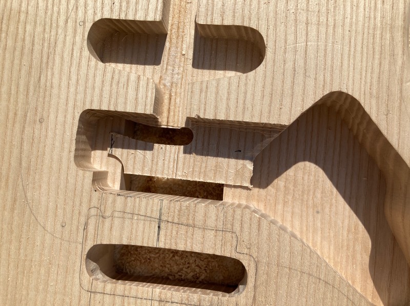
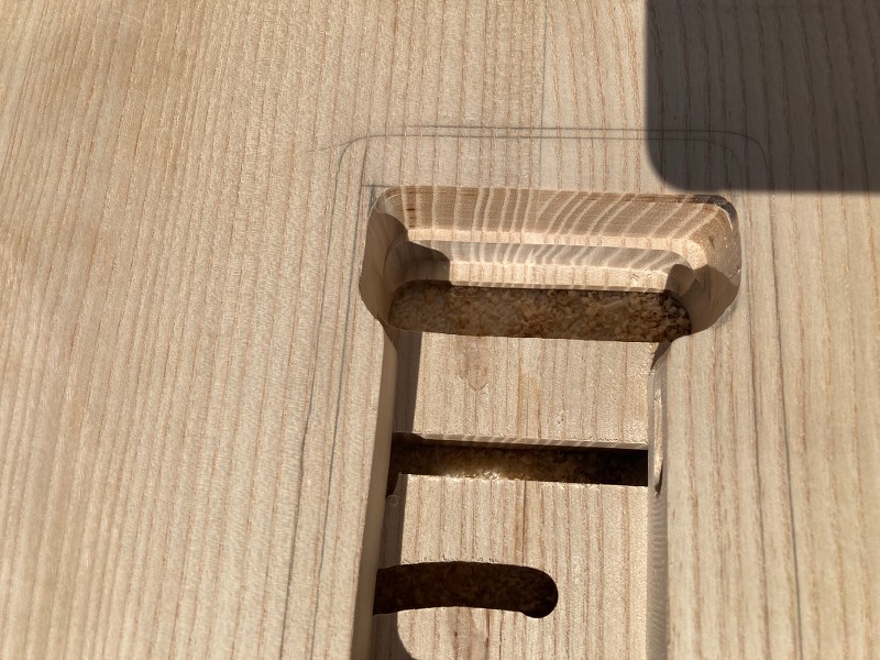
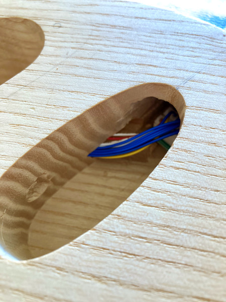
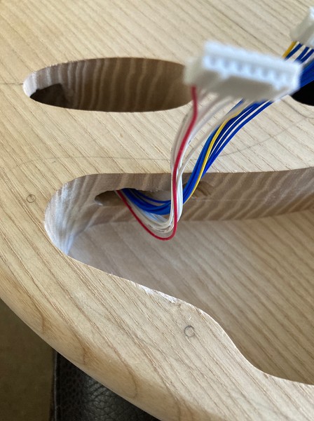
    Managed to do a bit indoors yesterday and today, so I now have a channel between the main control cavity and the jack plate cavity through which the 13-pin connector wires and headers fit.

    I drilled two holes a few mm apart from the control cavity to the jack socket cavity, using a 300mm long drill bit in order to get the smallest amount of angle I could, and then used a chisel to remove the wood that remained between the two holes. By sheer luck, the two holes both emerged right at the bottom of the jack cavity. I then cleaned the edges up with the smallest diameter Dremel drum sander bit I had (pics below were taken before the Dremel stage) and it's all looking good.


    Now for the post holes!

Page 2 of 8 FirstFirst 1 2 3 4 ... LastLast

Posting Permissions

  • You may not post new threads
  • You may not post replies
  • You may not post attachments
  • You may not edit your posts
  •