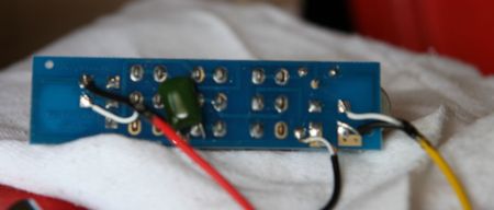
I don't know anything about the PCB in the
HB-4 (assuming it is a PCB as the kit photos don't show the underside of the switch panel) but if you can test it out with a multimeter or continuity buzzer, and they are connected, then no, no reason why not.
Whilst the PBG wiring diagram shows long lengths of the shield wire going to the common ground point, it's best if you can use either heatshrink insulation, some outer insulation wire covering or even insulation tape to cover long shield wires, to make sure that they don't accidentally touch a signal connection when installed and floating about inside the guitar, and so cause sound loss.


 Reply With Quote


 .
.

 .
.
 )
)
") ).
).