Page 2 of 7 FirstFirst 1 2 3 4 ... LastLast
Results 11 to 20 of 66

Thread: First build Explorer EXM-1

  1. #11
    GAStronomist FrankenWashie's Avatar
    Join Date
    Jan 2016
    Location
    Glebe, NSW
    Posts
    5,666
    Quote Originally Posted by Alexej View Post
    Second theme is, that I do not want PUS coverings, similar to the project of wazkelly https://goo.gl/KSY9W9
    I want to use some Aluminium bolt, to fill the lower niches under the PUS, to drill proper and stabile holes for the screws, using the springs betweet the PUS and the Aluminium to keep it adjustable. So my question is, if the Aluminium could have some effect on the sound, did someone had experience with that? For it is not magnetic, but maybe could still have some negative impact?

    Attachment 36184
    i have used brass plates under the PUPs in this build: https://www.buildyourownguitar.com.a...t=7399&page=17

    i haven’t noticed any issues, and the blocks I used go the full width of the PUP cavity. If you are only filling the screw rebate I don’t see it should be a problem, especially with aluminium.

    I am also going to use some M2 threaded brass inserts as PuP mounts for a later build. They are similar to these ones used in my current strat build: https://www.buildyourownguitar.com.a...t=8238&page=14
    FrankenLab
    Hand crafting guitars, because Death Rays are expensive.


  2. Liked by: Alexej

  3. #12
    Member
    Join Date
    Jun 2020
    Location
    Berlin, Germany
    Posts
    113
    Quote Originally Posted by FrankenWashie View Post
    i have used brass plates under the PUPs in this build: https://www.buildyourownguitar.com.a...t=7399&page=17

    i havenÂ’t noticed any issues, and the blocks I used go the full width of the PUP cavity. If you are only filling the screw rebate I donÂ’t see it should be a problem, especially with aluminium.

    I am also going to use some M2 threaded brass inserts as PuP mounts for a later build. They are similar to these ones used in my current strat build: https://www.buildyourownguitar.com.a...t=8238&page=14
    Hi. Thank you! I also thought that it should not be a problem, but read before of some issues, that different materials could cause vibrations, noise and stuff...so I am glad I can go on with the aluminium 
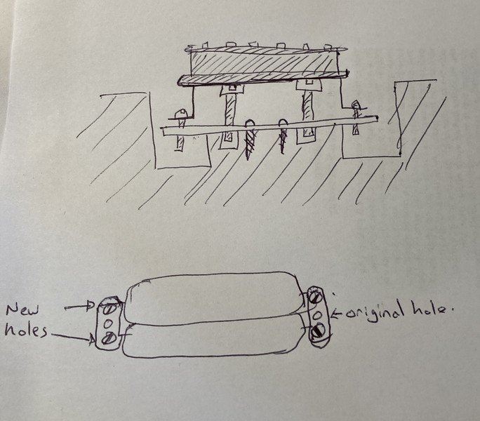
otherwise I think wood was just too weak for the screws and springs and it would take damage some day and be without use...so metal sounds a better solution

  4. #13
    GAStronomist Simon Barden's Avatar
    Join Date
    Oct 2016
    Location
    Reading, UK
    Posts
    10,547
    Aluminium is fine. Any non-magnetic metal is fine. As Frankenwashie mentioned, you may find that an aluminium bar is a lot easier to install than two blocks. You can screw the bar to the wood in the middle of the pickup rout. I'd consider making two holes either side of the existing central adjustment hole on the pickup leg, so that you can tap a thread into four matching holes in the aluminium bar. This means the original hole can still be used if you ever swap the pickups out and use them in another guitar. The four screws allow you to adjust the angle of the pickup. Rather than use a hard foam block or springs foam, you could tap some holes for a couple of flat headed screws that sit under the pickup to set its height.


    The four mounting screws then pull the pickup down hard onto the screws, so the pickup is mounted firmly in place for maximum connection to the body.

    You certainly want to position the neck so that the strings run down parallel to the sides of the neck. You may be better fitting a piece of veneer to one side of the neck pocket and sanding that down so the neck is kept at the right angle rather than tying to adjust it and glue it at the same time.

  5. Liked by: Alexej

  6. #14
    Member
    Join Date
    Jun 2020
    Location
    Berlin, Germany
    Posts
    113
    Quote Originally Posted by Simon Barden View Post
    Aluminium is fine. Any non-magnetic metal is fine. As Frankenwashie mentioned, you may find that an aluminium bar is a lot easier to install than two blocks. You can screw the bar to the wood in the middle of the pickup rout. I'd consider making two holes either side of the existing central adjustment hole on the pickup leg, so that you can tap a thread into four matching holes in the aluminium bar. This means the original hole can still be used if you ever swap the pickups out and use them in another guitar. The four screws allow you to adjust the angle of the pickup. Rather than use a hard foam block or springs foam, you could tap some holes for a couple of flat headed screws that sit under the pickup to set its height.


    The four mounting screws then pull the pickup down hard onto the screws, so the pickup is mounted firmly in place for maximum connection to the body.

    You certainly want to position the neck so that the strings run down parallel to the sides of the neck. You may be better fitting a piece of veneer to one side of the neck pocket and sanding that down so the neck is kept at the right angle rather than tying to adjust it and glue it at the same time.
    Thank you for the advices. I also had a bar first in mind, but then thought maybe it was too thin to get proper thread. Maybe using 3mm will be fine I think. I also like the 4 holes idear instead of two, to be able adjusting the angle of the PUPs, that's a good point. I will try it out

    More concerns I have about the neck, I have to measure it not twice but ten times before gluing 🙂

  7. #15
    GAStronomist Simon Barden's Avatar
    Join Date
    Oct 2016
    Location
    Reading, UK
    Posts
    10,547
    You may need to bend the bar into a dog-leg to accommodate the pickup legs, otherwise the pickup height may be too great. It depends on whether your pickups have short or long legs.

    The pickup legs themselves are probably 0.5mm thick brass, so the bar doesn't need to be too thick . The pickups mainly sit on the two height-adjustment screws in the middle, so the pickup leg screws are only there to help hold the pickup on to them.

    Don't assume that the end of the fretboard is at a perfect 90° to the centreline of the neck. You may need to sand it slightly to get it like that.

  8. #16
    Member
    Join Date
    Jun 2020
    Location
    Berlin, Germany
    Posts
    113
    Quote Originally Posted by Simon Barden View Post
    You may need to bend the bar into a dog-leg to accommodate the pickup legs, otherwise the pickup height may be too great. It depends on whether your pickups have short or long legs.

    The pickup legs themselves are probably 0.5mm thick brass, so the bar doesn't need to be too thick . The pickups mainly sit on the two height-adjustment screws in the middle, so the pickup leg screws are only there to help hold the pickup on to them.

    Don't assume that the end of the fretboard is at a perfect 90° to the centreline of the neck. You may need to sand it slightly to get it like that.
    Thx, I definitely like the suggested PUPs construction!
    For the high of the PUPs legs I am not sure, think I want some EMGs (battery case will be one more thing to do) installed later, but first the guitar has to be built right. The EMGs have small legs I think. But with the construction everything should be adjustable.

  9. #17
    Member
    Join Date
    Jun 2020
    Location
    Berlin, Germany
    Posts
    113
    Going forward, slowly, adjusting the neck.
    Had to add some piece of veneer to get the right angle for the body/neck. Now the neck is fitting tight and the strings seem to be in a right position. I think I can go on with sending and grain filler.
    When finished with that I will finally glue the neck to the body.
    For the color will be a solid black, I think all the glued pieces of veneer will be no problem, when smoothly sanded on one level with the body and neck surface. The only problem could be the veneer at the end of the fingerboard. Have to work on that carefully...

    Click image for larger version. 

Name:	Neck4.jpg 
Views:	159 
Size:	482.5 KB 
ID:	36395Click image for larger version. 

Name:	Neck5.jpg 
Views:	148 
Size:	353.9 KB 
ID:	36396Click image for larger version. 

Name:	Neck6.jpg 
Views:	159 
Size:	382.1 KB 
ID:	36397

  10. #18
    Member
    Join Date
    Jun 2020
    Location
    Berlin, Germany
    Posts
    113
    Another interesting thing to find was the space under the nut. Thinking about to fill some more veneer, to fill it, otherwise I do not know how to close that gap. Then again sanding the veneer to the level of the original neckwood...
    Quiet good to sand the veneer, when you tape one side and sand the other, otherwise it might break for its too thin...

    Click image for larger version. 

Name:	Nut.jpg 
Views:	156 
Size:	311.4 KB 
ID:	36398

  11. #19
    Member
    Join Date
    Jun 2020
    Location
    Berlin, Germany
    Posts
    113
    Lot of work besides the guitar...But coming forward...

    Built the bars for the PUPs holdings. Combined the advices and adapted them to my needs. Just wanted to let the EMGs in their original condition, without drilling new holes...so I am going for smaller screws, which go directly into the aluminium bar. Still adjustable in height, using some kind of foam. The angle of the PUPs ist quiet small, so I glued a piece of veneer on one side of the bars, so I get the PUPs parallel angled to the strings. Should fit I hope

    Click image for larger version. 

Name:	PUP1.jpg 
Views:	145 
Size:	489.8 KB 
ID:	36987
    Click image for larger version. 

Name:	PUP2.jpg 
Views:	156 
Size:	617.5 KB 
ID:	36988
    Click image for larger version. 

Name:	PUP3.jpg 
Views:	171 
Size:	494.1 KB 
ID:	36989

  12. #20
    Member
    Join Date
    Jun 2020
    Location
    Berlin, Germany
    Posts
    113
    For the EMG electronics need a lot of space, and the battery also... I had to do some milling...for the first time in my life...almost fucked up the whole thing...but at the end it worked...I am glad the body will be black, so my mistakes will be invisible after grainfilling and modeling with wood putty...

    made also individual coverings and put some nuts inside the wood for the screws...Those are used in 3D printed stuff, as far as I have seen, but do a good job in woodworking...

    Click image for larger version. 

Name:	Electronics1.jpg 
Views:	152 
Size:	485.3 KB 
ID:	36990
    Click image for larger version. 

Name:	Electronics3.jpg 
Views:	152 
Size:	360.5 KB 
ID:	36991

Page 2 of 7 FirstFirst 1 2 3 4 ... LastLast

Posting Permissions

  • You may not post new threads
  • You may not post replies
  • You may not post attachments
  • You may not edit your posts
  •