Page 1 of 2 1 2 LastLast
Results 1 to 10 of 12

Thread: TL-1 wiring trouble

  1. #1

    TL-1 wiring trouble

    I got my TL-1 kit about a week ago (my first guitar kit) and I’m now in the wiring stage. I have soldered the neck and bridge pickup hot wires to the switch, and the pickup ground wires to the volume pot. I then wired up my output jack, hot to tip and ground to sleeve. I then put the ground wire coming off the volume pot under my bridge plate. After this, I tested it by hooking it up to an amp and tapping both pickups with a screwdriver, and I got no sound at all. As soon as I plugged the lead in it went completely silent.

    I think that I got my wiring right, but maybe it’s a soldering issue.

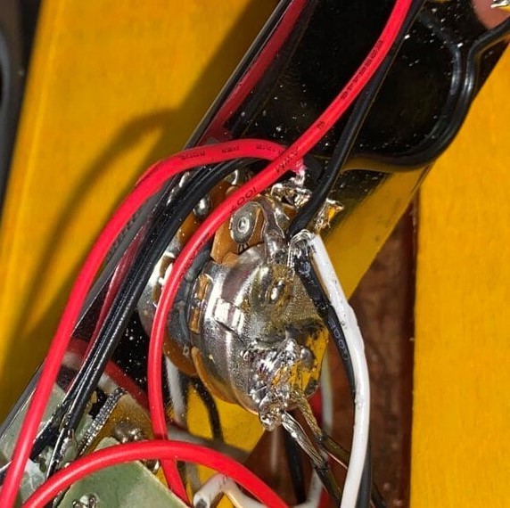
    I also struggled with the wiring as the colours of my wires didn’t match up with the diagram or the YouTube video. I used red and white - hot, and black wires - ground (except for a red wire coming off the volume pot which I think is the ground wire you sit under the bridge plate.) I would really appreciate if someone could help me as it’s really frustrating and I just want to play it.

    Cheers!

  2. #2
    GAStronomist Simon Barden's Avatar
    Join Date
    Oct 2016
    Location
    Reading, UK
    Posts
    10,547
    Hi and welcome.

    It sounds like you've done the right things, but it's hard to tell what's going on without a photo. The factory may have missed a wire connection.

    Just a sanity check, but you did have the volume and tone controls turned up? I've spent a while looking for faults when it was either the guitar or amp volume that was turned down!

  3. #3
    Overlord of Music WeirdBits's Avatar
    Join Date
    Jan 2013
    Posts
    2,731
    Copper shielding? And, if so, did you perhaps shield the inside of the hole for the output jack?
    Scott.

  4. #4
    Click image for larger version. 

Name:	IMG_0928 (1).jpg 
Views:	174 
Size:	234.8 KB 
ID:	34567
    Click image for larger version. 

Name:	IMG_0929 (1).jpg 
Views:	166 
Size:	256.0 KB 
ID:	34568
    Click image for larger version. 

Name:	IMG_0930 (1).jpg 
Views:	146 
Size:	209.8 KB 
ID:	34569
    Click image for larger version. 

Name:	IMG_0931 (1).jpg 
Views:	149 
Size:	296.6 KB 
ID:	34570

    There are some photos mate, sorry I didn't upload them before - I didn't know how to. But I did make sure to have the volume and tone controls turned up. Thanks for your help I really appreciate it

  5. #5
    I did shield the cavities, but no I didn't shield the output jack hole - I ran out of tape.

  6. #6
    GAStronomist Simon Barden's Avatar
    Join Date
    Oct 2016
    Location
    Reading, UK
    Posts
    10,547
    It looks to me like the red wire that you are running under the bridge plate is the output wire from the volume pot. It looks like the white and black wires you have going to the output jack are both soldered to the back of the volume pot, and so are both ground wires. Check this - confirm that the red wire comes from the middle tag of the volume pot and the white wire is soldered to back of the volume pot. If so, I'd swap the white and the red wires around, so the red wire goes to the tip connection of the jack socket and the white grounds the bridge plate.

    If this isn't so, then I'd really like a clearer look at the volume pot connections and a photo showing the three solder tags and the connected wires on that volume pot.

  7. #7
    As been mentioned by others elsewhere, you should tap the pickups before screwing it all in place.
    Then you'll know if it's the shielding that's shorting out.

    cheers, Mark.

  8. #8
    GAStronomist Simon Barden's Avatar
    Join Date
    Oct 2016
    Location
    Reading, UK
    Posts
    10,547
    Having a closer look, I'm pretty sure that it's the red and white wires that simply need to be reversed. That red wire is definitely the volume pot output wire.


  9. #9
    Overlord of Music fender3x's Avatar
    Join Date
    Jan 2016
    Location
    Miami, FL, USA
    Posts
    2,206
    I can't see it very well in the pic, but I think Simon is right about the red wire. That's assuming that the only thing attached to the middle post is the red wire that goes to the bridge, and that the white wire to the jack is grounded (earthed) with the black wire to the jack.

    If that doesn't solve the problem, it may be that you have sent the signal to ground some other way. A possible culprit is the hot lead from the switch. The hot lead coming off the switch is the black wire...but I can't see where it attaches. It *should* attach to the outside lug that is not grounded to the casing. The only other lead coming off this lug is the wire that goes to the tone pot.*

    It looks like you have a red and a black wire soldered to the casing of tone pot. The black one seems to be soldered to the white and the black wires that go to the jack (so only grounds going to the jack if this is right). The red wire, also a ground, seems to appears to go to the ground lug on the switch.

    Your opening post has exactly the right idea "I used red and white - hot, and black wires". When I don't observe this rule, I almost always solder something to the wrong terminal.

    The problem is that they appear to be reversed in places. You're white pup lead to the switch looks right. Your red pup lead to the switch looks right too. The two black wires from the pups are grounded, as they should be. But the hot wire from the switch is black. You also have a black "hot" wire going to the tone pot. You have two ground wires coming back from the tone pot, one red and one black. The red one goes to ground the switch... also on the switch you have a black wire that connects the terminals on the right and the left of the center terminal. I don't think that is doing anything at all, but if it were me, I would remove it to avoid thinking that it is a ground wire (which it is not). Then the root of the problem if Simon is right (he usually is), that the "hot" white wire to the jack had been grounded to the volume pot case. I would also replace the red wire from the bridge with a black one, since it is a ground wire.


    *Tone pot looks like the lugs are reversed from what you see in most charts but it may not make a difference and is definitely not the root of the problem.
    Last edited by fender3x; 17-04-2020 at 03:12 AM.

  10. #10
    Overlord of Music McCreed's Avatar
    Join Date
    Oct 2018
    Location
    AUS
    Posts
    3,552
    My assessment is also the red & white wires as Simon pointed out.
    Making the world a better place; one guitar at a time...

Page 1 of 2 1 2 LastLast

Posting Permissions

  • You may not post new threads
  • You may not post replies
  • You may not post attachments
  • You may not edit your posts
  •