Page 16 of 19 FirstFirst ... 6 14 15 16 17 18 ... LastLast
Results 151 to 160 of 185

Thread: Teleburster TL-1A aka G-special

  1. #151
    Ok guys, you've talked me into it, I'll post up a separate thread about making templates and cutting pickguards etc. I need to get a few more pics to explain a couple of things, but I should get it sorted in the next few days.

    Back to the build…

    The final step in my shielding was to add a touch of electrical insulation over the shielding where the switch will sit in the control cavity and beneath the neck pickup. Neither should touch, but the switch is very large and the neck pickup will be sitting very low, so I just wanted a little insurance.


    Regarding the neck pickup (GFS Lil' Puncher XL), it is recommended that it be mounted low, real low, like pickguard level low, to allow it to 'breathe' (their description). I took this into account from the start of the build, which explains why I had that strange looking extra bit of routing in the neck pup cavity. But, because it will be sitting so low and it will be body mounted, the normal pickup springs and screws would either leave it sitting too high or the screws would risk being too deep. Instead, I made some spacers from hard plastic tube that will be on the screws above the pickup, and used surgical rubber instead of springs. The spacers keep the screws from needing to go too deep and the rubber allows the pickup to be really low but still have just enough flex so the pickguard can be slid in/out of position.


    And screwed into position. Note: before I mounted the pickup I quickly de-soldered and separated the series link of the coils (4 conductor), ready for wiring later.


    Scott.

  2. #152
    When I started the build I was considering doing coil splits etc. on these pickups, but apparently the results aren't ideal. From what I can gather the bridge split sounds the same but weaker, while the neck split washes out completely (or, so the reports go). Instead, I decided to try series/parallel coil switching for each pickup, and series and parallel options between the pickups. Here's the wiring scheme I eventually came up with (I couldn't be bothered re-doing it on the PC). The circled letters (ABCD) denote the 4 poles of the switch.


    Note, there is an slight error in the above schematic. The 'GFS Colours' list in the upper left should be:
    Green (hot)
    Red
    &
    White
    Black (gnd)

    This change means the the red and white wire connections on the push/pull pots need to be reversed, so white goes to the middle terminal, red to the outer terminal on the same side.


    Specs: GFS Lil' Puncher XL pickups (Cool Vintage version), 500K Alpha push/pull pots (log for volume, linear for tone), 0.047uF paper in oil cap, Grigsby 4-pole 5-way superswitch, and post-volume tone wiring.

    Basically, the push/pull pots allow the pickup coils to be switched between series and parallel, which should thin/hollow and brighten their sound, and the 500K pots should help keep the overall brightness. The superswitch allows me to not only do the "Tele 4-way bridge and neck in series" option, but also the bridge and neck in parallel out of phase. Positions 1, 3 and 5 will give the standard Tele options, with the extras at positions 4 and 2, respectively. At least, that's the plan… it may change depending on how it sounds.

    I wanted the control plate to be complete as possible ready for when the bridge, and bridge pup, is installed, but I can only go so far. The four wires of each pickup need to connected to the push/pull switches on the pots, but that can only be done with the pickups in place, which is going to be a real pain to do. Anyway, all the wiring and links are now in place on the plate, and it's just waiting for the pickups and output jack lead to be connected. It's a little messier that I'd like, but I had to be more concerned about minimising the profile of the switch than making it pretty.


    I couldn't bring myself to clip the leads on the PIO cap, it's a little too permanent and would restrict where I could position it, so instead I slid on some stripped insulation and now I should be able to position it where I want without risk of a short. The keen eyed may notice that the wiring on one of the switches doesn't match my diagram, it's just that I reversed it so that it will be easier to access when I connect the pickups.

    I did a continuity check and everything appears to be connected and working the way it should be. I also checked the pots, 439K for the log volume pot, and 498K for the linear tone pot. The volume is a little low, but I can live with it.


    Scott.

  3. #153
    Mentor
    Join Date
    Aug 2013
    Location
    Mackay
    Posts
    1,276
    Wow Scott. I've done a fair bit of intense wiring in tight spaces and that is definitely up there with them. Only jiggle space left. You wiring schematic is fantastic and is going to provide so many options from a 'simple' setup. Brilliant. 8-)

  4. #154
    hehe thanks Lawry… I think that may turn out to be one of my tamer schematics

    In what I think will be one of the final steps before I bolt everything together, I had a go at making my first nut today (unbleached bone). I suppose it would be much easier if the neck was already on, but I knew if I put it together with a temporary nut it would most likely end up being a permanent temporary nut. I basically followed the StewMac Nut Making Guide as closely as I could, and used other nuts I had for reference. It's definitely a skill that will take time to develop to produce quality results, so full admiration to professionals like Gav and DB who actually know what they're doing.

    I cut the nut, what I hope is, a fraction high so that it can be lowered as needed. It's not a great first effort, but it looks ok and I think it will be usable. I haven't trimmed the nut's width yet, which will wait until the neck is bolted on, and then I'll do the final adjustment and clean-up… at least, I will if it is actually usable. We'll see. If all else fails I still have the original plastic nut that I removed intact at the start of the build.

    Adjusting the thickness of the blank to match the nut slot.


    With the initial shaping done, marking out string positions.


    And the result so far. Tough to get a good pic that actually showed the shape and slots, so this is the best I could manage. I'll see how it goes once the neck is on.


    Scott.

  5. #155
    Moderator Gavin1393's Avatar
    Join Date
    Sep 2012
    Location
    Mindarie, Western Australia
    Posts
    3,152
    I think the first one I ever did took me 90 minutes or more.... whack one out from start to finish in under 15 minutes these days. So there's hope!
    http://www.buildyourownguitar.com.au/forum/image.php?type=sigpic&userid=1258&dateline=1443806  448Gavmeister

  6. #156
    Overlord of Music gavinturner's Avatar
    Join Date
    May 2013
    Location
    HOLGATE NSW
    Posts
    3,057
    Great job Scott. I've done 2 nuts so far and it's still a struggle, especially the final adjustment. Looks like you've totally nailed it!

    cheers,
    Gav.
    --
    Build #01: BC-1
    Build #02: ST-1
    Build #03: JR-1DC
    Build #04: ES-2V
    Build #05: ESB-4 (GOTM July 2014)
    Build #06: RC-1
    Build #07: MK-2
    Build #08: TLA-1
    Build #09: JR-1DC
    Build #0A: LPA-1
    Build #0B: STA-1 (GOTM April 2015)
    Build #0C: MKA-2
    Build #0D: LP-1M
    Build #0E: JB-1
    Build #0F: FS-1

    Find me:
    https://www.facebook.com/firescreek.guitars/
    http://www.guitarkitbuilder.blogspot.com.au/

  7. #157
    Mentor AJ's Avatar
    Join Date
    Mar 2013
    Location
    Hoppers Crossing, Melbourne
    Posts
    562
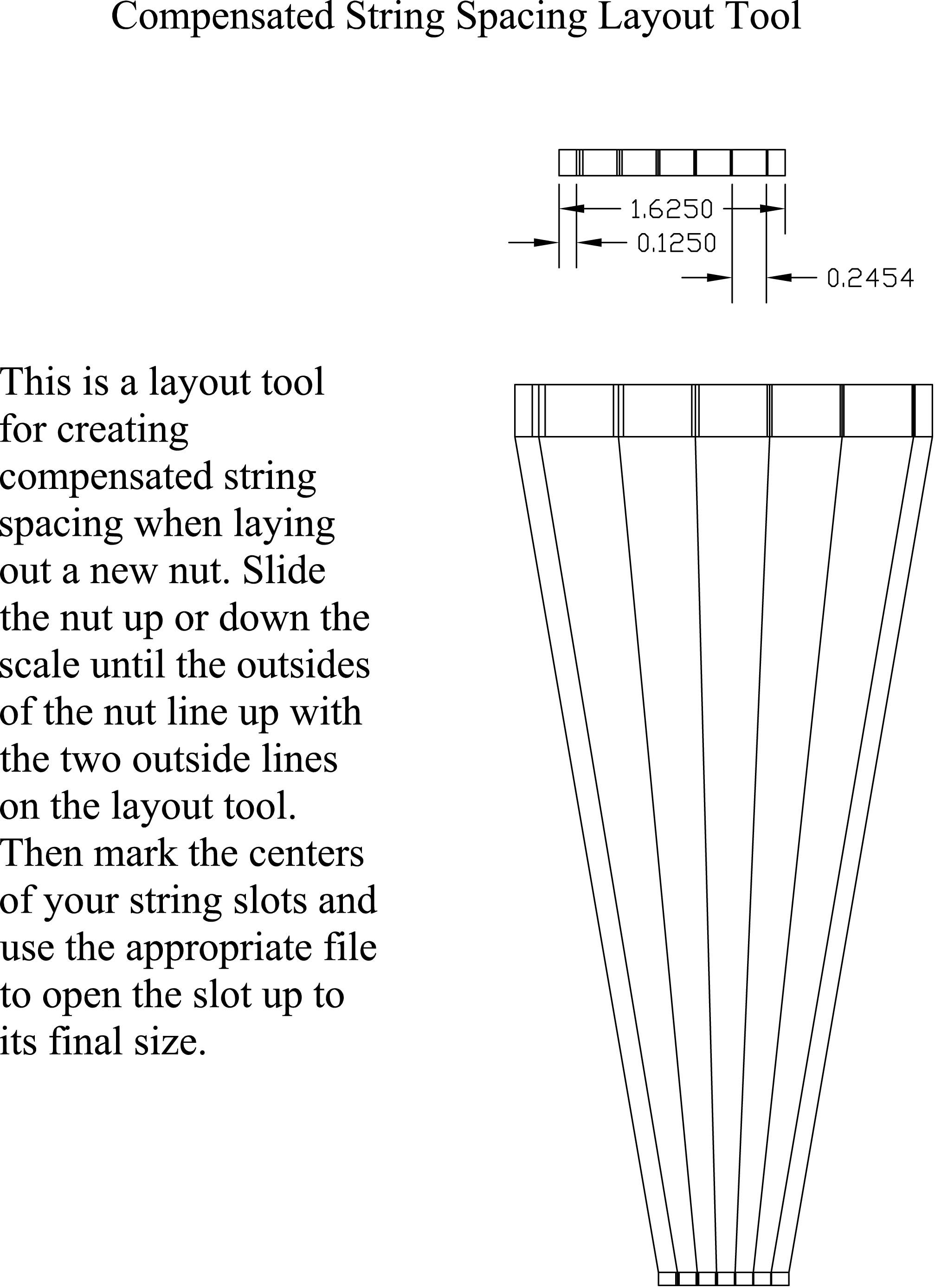
    Looking good there, and there's nothing like the feeling that you made the nut from "get go" all yourself.. and for those that don't have a stewmac string spacing rule, I found this on the net a little ways back and it is as close as you can get to the stew mac spacings.. just slide the nut down the scale till the two outside marks line up and bingo.. you got all the strings evenly compensated/ spaced.
    Projects:
    LP-1A
    TL1-A
    LP-1Completed
    TL-1Completed
    Yamaha rebuild: Completed
    Mako -Scratch designed: Completed
    PUP winder: Completed

    Facebook : www.facebook.com/andrew.johns.1272010
    Skype: andyjohns1

  8. #158
    Mentor AJ's Avatar
    Join Date
    Mar 2013
    Location
    Hoppers Crossing, Melbourne
    Posts
    562
    the pdf didn't upload first time, converted it to a jpg file.
    Projects:
    LP-1A
    TL1-A
    LP-1Completed
    TL-1Completed
    Yamaha rebuild: Completed
    Mako -Scratch designed: Completed
    PUP winder: Completed

    Facebook : www.facebook.com/andrew.johns.1272010
    Skype: andyjohns1

  9. #159
    Mentor AJ's Avatar
    Join Date
    Mar 2013
    Location
    Hoppers Crossing, Melbourne
    Posts
    562
    3rd go.. next time should get the next doors kid to show me how to..lol
    Projects:
    LP-1A
    TL1-A
    LP-1Completed
    TL-1Completed
    Yamaha rebuild: Completed
    Mako -Scratch designed: Completed
    PUP winder: Completed

    Facebook : www.facebook.com/andrew.johns.1272010
    Skype: andyjohns1

  10. #160
    Overlord of Music gavinturner's Avatar
    Join Date
    May 2013
    Location
    HOLGATE NSW
    Posts
    3,057
    Nice one AJ!

    cheers,
    Gav.
    --
    Build #01: BC-1
    Build #02: ST-1
    Build #03: JR-1DC
    Build #04: ES-2V
    Build #05: ESB-4 (GOTM July 2014)
    Build #06: RC-1
    Build #07: MK-2
    Build #08: TLA-1
    Build #09: JR-1DC
    Build #0A: LPA-1
    Build #0B: STA-1 (GOTM April 2015)
    Build #0C: MKA-2
    Build #0D: LP-1M
    Build #0E: JB-1
    Build #0F: FS-1

    Find me:
    https://www.facebook.com/firescreek.guitars/
    http://www.guitarkitbuilder.blogspot.com.au/

Page 16 of 19 FirstFirst ... 6 14 15 16 17 18 ... LastLast

Posting Permissions

  • You may not post new threads
  • You may not post replies
  • You may not post attachments
  • You may not edit your posts
  •