
Hello: I am looking for a tutorial or help for the PB-30R DIY Electric Bass Guitar Kit 30. Thank you very much


Hello: I am looking for a tutorial or help for the PB-30R DIY Electric Bass Guitar Kit 30. Thank you very much

Hello Tino! Sorry for the delay in getting back to you. I think you are asking about how to solder your the wires on your kit? You can use the "Precision Bass" wiring diagram from the PitBull website... but it is a little incompleteOriginally Posted by Tino

https://www.pitbullguitars.com/wp-co...-PB-4%20v2.pdf
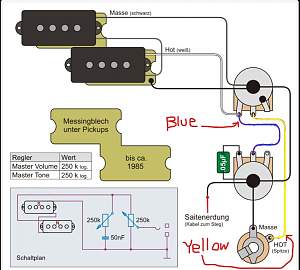
This one is a little clearer...
It's in German, but there's not much to translate: "Masse" refers to "ground" or "earth." The other is "Saitenerdung" this means "bridge ground wire"
I like this chart better because it shows the ground wires which the PitBull diagram does not.
Did any of your kit come pre-wired? If so, you may just need to attach the pickups and the bridge ground wire.
If it is not pre-wired, you need to hook up all the wires. I found a video that is pretty complete here...
I found two videos specifically about wiring a Precision Bass, which is what your bass has. This was the better of the two, but there are some things about it that are odd. He is using old pots that have been soldered before, and are quite dirty. Also he is using a GIANT capacitor (cap). In your kit it will be MUCH smaller and either a "burnt orange" color or green as in the diagram I sent. It does not need to be very big to work ;-)
One thing to note is whether your bass has a hole drilled from under the bridge to the control cavity. It looks like it does on the PitBull website, but sometimes they come without the hole being pre-drilled so that you will need to drill it yourself. That wire is very important for grounding the strings.
If any of this is confusing, feel free to post a picture and ask questions along the way. We have had folks that are pretty expert with electronics, as well as people who have never soldered wires before, so all questions are OK ;-)
Thank you very much for your very complete and detailed response. I am sending you a photo of the kit that arrived to me. I think that with the information you sent me I wouldn't have any problem making the solderings. One of the pickups came detached. I suppose I should glue it. Sorry if my English is not correct, I am using Google Translate and I don't know if any word or expression will be correct.
Cheers and good luck.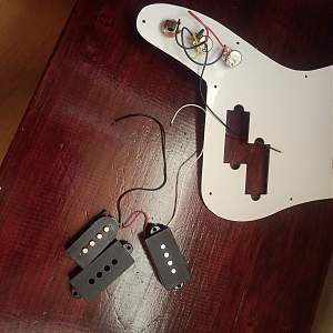
OK! So some good news. It looks like most of the soldering is already done. It is a bit odd they way they did it at the factory. Their color choices are a bit odd, but it all looks correct. To connect the pickups:
1) Solder the white wire from the pickup to the post that has the blue wire attached on the first potentiometer (the one closest to the pickup hole). When you do that, the blue wire may become detached. You need to make sure both the white wire from the pickup and the blue wire are attached to the post the blue wire is currently attached to.
2) Solder the black wire to the back of the same potentiometer.
That should be it!
It looks like one of the covers has come off of one of your pickup bobbins. You can just put it back together. There are two ways to install the pickups on the bass. You can put a small piece of foam under the pickup, so that it sits a little higher than you want it to, and then use the screws to adjust the pickup height under the strings.
Alternatively you can do it the traditional way by using small steel springs on the bridge screws. Your kit should have come with either springs or foam or both. Some pickups come with small pieces of surgical tubing that would be used just like the springs. Most people on the forum seem to like foam best, and it might work best in your case since the cover has come loose from the the pickup. But if you want to use the springs you will need to make sure pickup stays in the cover. I can't tell in the picture if they used glue or wax to bond the cover to the bobbin. If it's glue you can use a bit of CA (superglue) to put them back together. If it's wax, the glue won't stick...and I would just use a foam spacer under the pickup.
Before you attach the pickguard and pickups, it's best to shield the body and pickguard. Shielding is optional, but helps keep the bass from picking up radio waves (basically noise) through it's electronics. Here's a video of someone shielding a bass:
If you don't have copper tape you can get it at many stores that sell hardware or outdoor plants. It is often sold as a way to keep snails out of the garden. You can also order it on-line from places that sell guitar parts. Please note, you only need to put a little shielding around the pickup holes and over the control cavity. It is not necessary to cover the entire back of the pickguard with shielding tape. That's just a waste of tape.
Most copper tape uses conductive adhesive, but you may need to check that with a cheap multimeter. I have one like this that cost me about $8, and works well for this.
That covers everything except the stray black wire...
Last edited by fender3x; 13-05-2026 at 01:01 AM.
...the stray black wire which is attached to the tone potentiometer (pot), is for grounding your bridge. Here's a video of someone doing that:
Hopefully your bass comes pre-drilled with a hole under the bridge that runs to the control cavity. If you are not sure whether you have this, send a picture of the top of the bass body. Or if you don't have it let us know. I have drilled these holes successfully several times, but I messed it up on my last bass. I was able to fix it, but it also prompted me to ask folks on the forum for a more fool-proof way of drilling, which I will be happy to share with you if you need to drill ;-)
Last edited by fender3x; 13-05-2026 at 01:02 AM.
Thank you very much, I will follow your instructions. Greetings from Galicia
Shielding looks good!
Ground wire to the bridge looks good too, although you could just use the black wire that is already attached to the back of the tone potentiometer (pot). Or you can just attach the new red wire to that black wire.
I think I see the problem on the tone pot. It looks like the yellow wire should be attached to the middle lug of the volume pot, rather than the tone pot. The yellow wire should go directly from the middle lug of the volume pot to the jack.
The blue wire and capacitor look correct, but the yellow wire should not go to the tone pot or touch the blue wire. Sorry I didn't catch that earlier!
Y saludos desde Miami ;-)
Last edited by fender3x; 13-05-2026 at 09:02 PM.
I will do it that way
That should work! Looks good ;-)
Sent from my CPH2655 using Tapatalk
 Posting Permissions

 Reply With Quote