


Thanks again Mccreed really appreciated.
While I wait for the additional copper tape to finish the control cavity I have been looking at the wiring - and am somewhat confused (it may be me or is the PB tstyle wiring missing some wires)
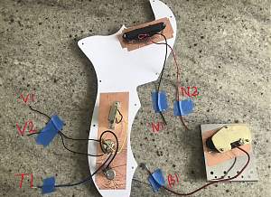
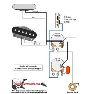
My understanding of the following wiring is that they are wired as follows - my google reference also below:
- T1 to Jack - white insulated wire to the and silver earth wire to the sleeve
- N1 to Volume pot and is a ground wire
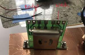
- N2 to Neck slot second from right end on switch (toward the rear of guitar)
- B1 to Bridge slot second from left on switch (toward the front of guitar)
- V1 to ??
- V2 to ??
Are V1 and V2 meant to connect to the PUP earth wires or indeed back to the PUP cavities to earth them?
Thanks again!


 Reply With Quote


