
Great diagram in the link you sent thank you. I will study that more. Hope I can get the guitar back soon.Originally Posted by jugglindan

So is The Basement still open up on the hill in Belco?


Great diagram in the link you sent thank you. I will study that more. Hope I can get the guitar back soon.
So is The Basement still open up on the hill in Belco?
Cheers,
Alkay
Build 1(LP Style): http://www.buildyourownguitar.com.au...ighlight=alkay - On Hold
Build 2(LP Style): http://www.buildyourownguitar.com.au...ighlight=alkay - Completed
Build 3(LP Style): http://www.buildyourownguitar.com.au...ighlight=alkay - Commenced
Build 4(RBX Style): http://www.buildyourownguitar.com.au...ighlight=alkay - Commenced

Yes, that Fralin link has the best explanation of how the switches work. Understand that and you can create any effect you want. I will be using that page's wiring for everything in the future.
Re The Basement: sorry, I don't know. I'm on the southside and only get to Belco maybe once a year when visiting Jaycar. Pretty much all bars, clubs, and music venues are closed right now though
Sorry, I missed this in my last reply.
Yes, you are correct. You just need one extra link wire on each side, to connect the red and green coloured terminals in the top-middle diagram to the output wire that heads off to the pots.
If you have some alligator clip test leads (or can hack something up with paperclips and wire) you can temporarily bridge the connections without soldering to make sure you have the right terminals identified. The DiMarzio diagram has the lug ordering reversed from the Fralin one, so I think one is looking from the top of the switch and one from the bottom. I tried to account for this, but testing with temporary connections is the safest approach.
Ok great thank you. I'll see if I can get it back over the weekend and give it a try.
Cheers,
Alkay.
Cheers,
Alkay
Build 1(LP Style): http://www.buildyourownguitar.com.au...ighlight=alkay - On Hold
Build 2(LP Style): http://www.buildyourownguitar.com.au...ighlight=alkay - Completed
Build 3(LP Style): http://www.buildyourownguitar.com.au...ighlight=alkay - Commenced
Build 4(RBX Style): http://www.buildyourownguitar.com.au...ighlight=alkay - Commenced
Ok I have the guitar back. Just to confirm it's the top middle of the diagram you did for me and NOT the bottom middle.
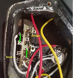
Here is a pic I have tried to label it the best I can I hope you can see?
Cheers,
Alkay
Cheers,
Alkay
Build 1(LP Style): http://www.buildyourownguitar.com.au...ighlight=alkay - On Hold
Build 2(LP Style): http://www.buildyourownguitar.com.au...ighlight=alkay - Completed
Build 3(LP Style): http://www.buildyourownguitar.com.au...ighlight=alkay - Commenced
Build 4(RBX Style): http://www.buildyourownguitar.com.au...ighlight=alkay - Commenced
So noted in the blue line below is where I should make a connection or have I stuffed that up hahaha?
Actually from reading I think this is the one I'm meant to be doing?
Last edited by Alkay; 24-04-2020 at 03:32 PM. Reason: stuffed up diagram
Cheers,
Alkay
Build 1(LP Style): http://www.buildyourownguitar.com.au...ighlight=alkay - On Hold
Build 2(LP Style): http://www.buildyourownguitar.com.au...ighlight=alkay - Completed
Build 3(LP Style): http://www.buildyourownguitar.com.au...ighlight=alkay - Commenced
Build 4(RBX Style): http://www.buildyourownguitar.com.au...ighlight=alkay - Commenced
Awesome just tried it with some trusty twist ties and it works perfectly. So I'll solder it now
Cheers,
Alkay
Build 1(LP Style): http://www.buildyourownguitar.com.au...ighlight=alkay - On Hold
Build 2(LP Style): http://www.buildyourownguitar.com.au...ighlight=alkay - Completed
Build 3(LP Style): http://www.buildyourownguitar.com.au...ighlight=alkay - Commenced
Build 4(RBX Style): http://www.buildyourownguitar.com.au...ighlight=alkay - Commenced
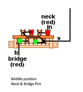
Your blue line doesn't look right to me. The second diagram is the one to aim for. Here's why:
This is the diagram just for the middle switch position, which should select both pickups. The red spots show which terminals on the neck pickup side are connected to each other in that switch position. The neck pickup wire connects to the other red terminal, but that is not connected to the output. It's the same on the bridge pickup side (green spots).
The bottom diagram shows the two additional links required to connect the each pickup to the output wire in this position. If you go back to the full diagram you can connect the green dots to see which switch position will include the bridge, and connect the red dots to see when the neck is connected. The purple circles just highlight the critical spots.
As far as I can tell from your photo, the two green lines I have drawn correspond to where you need extra links. But please test first without soldering if you can.
Mate.......awesome I did it. It worked and I am very happy with the result
Cheers,
Alkay
Build 1(LP Style): http://www.buildyourownguitar.com.au...ighlight=alkay - On Hold
Build 2(LP Style): http://www.buildyourownguitar.com.au...ighlight=alkay - Completed
Build 3(LP Style): http://www.buildyourownguitar.com.au...ighlight=alkay - Commenced
Build 4(RBX Style): http://www.buildyourownguitar.com.au...ighlight=alkay - Commenced
Very happy with that thank you so much. I wish I could help othhers on this forum but I'm still learning, especially about the electronics.
Only issue is I didn't have enough wiring from the neck pup so had to leave the orientation of the switch the same without trying to extend the PUP wires but he is happy now and I'm really happy that I learned. I encouraged him to get into guitar building too.
It's such a great community here and I thank everyone always for their input so thank you. I'm so happy
Cheers,
Alkay.
Cheers,
Alkay
Build 1(LP Style): http://www.buildyourownguitar.com.au...ighlight=alkay - On Hold
Build 2(LP Style): http://www.buildyourownguitar.com.au...ighlight=alkay - Completed
Build 3(LP Style): http://www.buildyourownguitar.com.au...ighlight=alkay - Commenced
Build 4(RBX Style): http://www.buildyourownguitar.com.au...ighlight=alkay - Commenced

 Reply With Quote