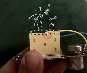
My first build, no experience. I have a tele kit with a 3 way switch I bought about a year and a half ago. I'm confused on wiring the pickups in to the control plate/switch. The diagrams and videos I've seen show a switch with 7 holes and the wiring is pretty self explanatory. However the switch in the kit I've got has 8 holes. I know where the neck pickup holes are, but which of the three holes in the "front" do I use for the bridge pickup?
7 hole switches are the same as 8 hole switches, except on the 7 hole switches, what would be the two middle holes of an 8 hole switch are already linked together on the switch PCB. On an 8 hole switch, those two middle holes need to be linked together with wire.
On an 8 hole switch, you've basically got two sets of contacts on one switch; a common output plus three inputs x 2. It's a more flexible arrangement as you can use it for different wiring arrangements if you move away from the standard configuration. A 7-hole switch simply removes the need to link the two central connections together if using standard wiring.
So just link and view the two central holes as one 'hole', and then the wiring of the others should be as for a 7 hole switch.


 Reply With Quote
