Slightly different design from the previous one I built. But this is the pick-up winder I am building for our good friend Dingobass!
Here is the recipe for this one.
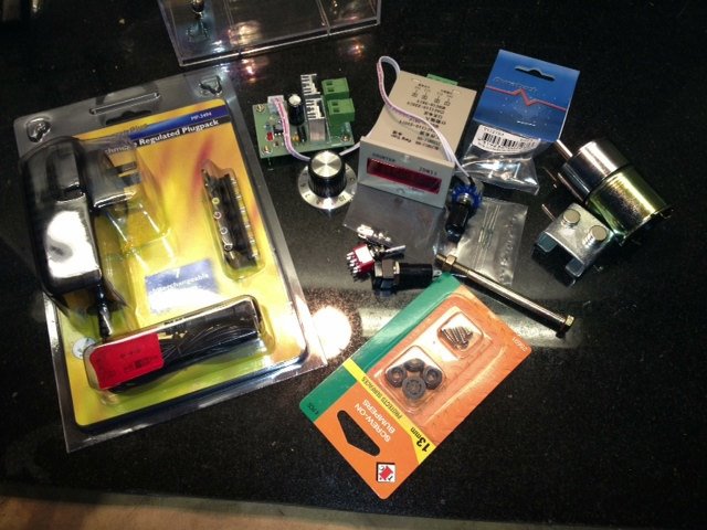
First throw in some Parts....


Slightly different design from the previous one I built. But this is the pick-up winder I am building for our good friend Dingobass!
Here is the recipe for this one.
First throw in some Parts....
Gavmeister
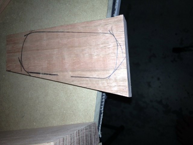
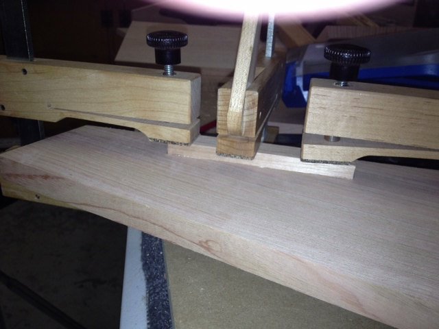
Buy some wood.....and mark it for the box and pickup holder.
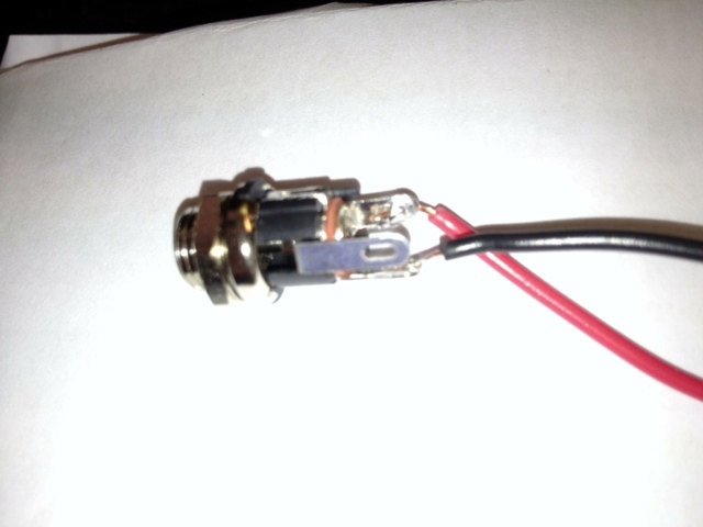
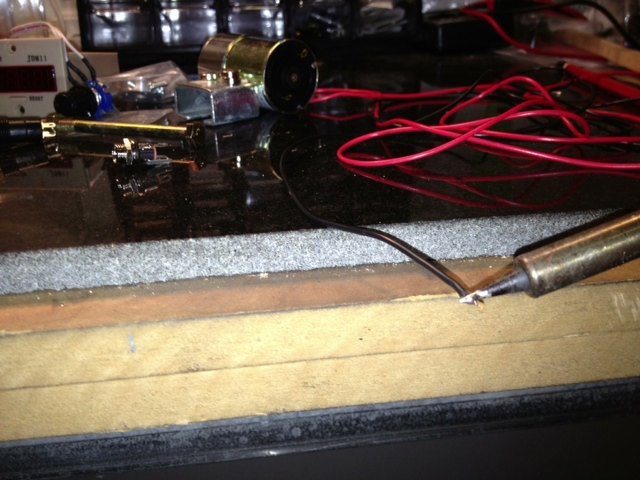
Grab some electronic wire and wick the ends with solder in preparation to attach to the power input socket.
Attach socket keeping polarity in mind. The 24v counter and motor controller will be attached at the opposite end.
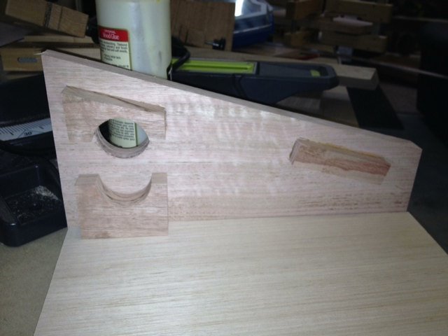
Building the box and cutting the pickup winder holder to shape. This is the 'empty side' of the winder. Simply seen here, gluing a support for the 'lid' of the winder.
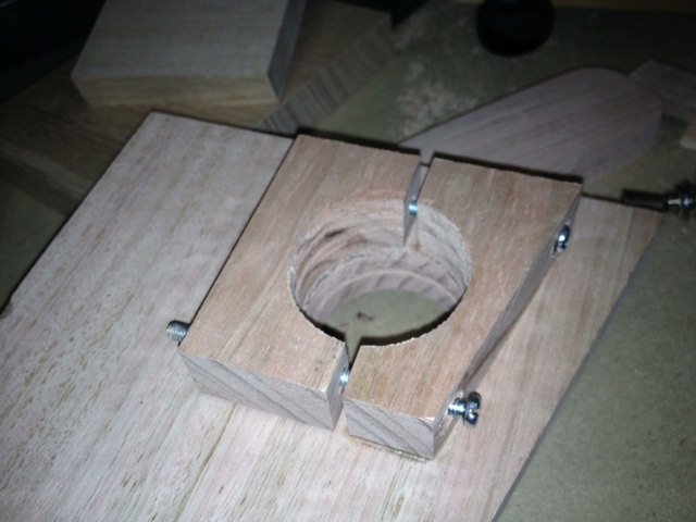
Below is the busy side of the winder after being glued. As you can see I have already drilled the cavity and cut the support which will house the 800 RPM motor. Still to come is the hole for the Reed Switch which will trigger the counter to count the revolutions as well as the 'feeder' that will be used to guide the wire onto the coil.
Note that part of the motor housing is actually loose at the moment. It is not glued to the side and won't be glued. The idea is that this component will be bolted into the glued section so that the motor aan be changed if ever something goes wrong or if the component needs to be shifted or updated.
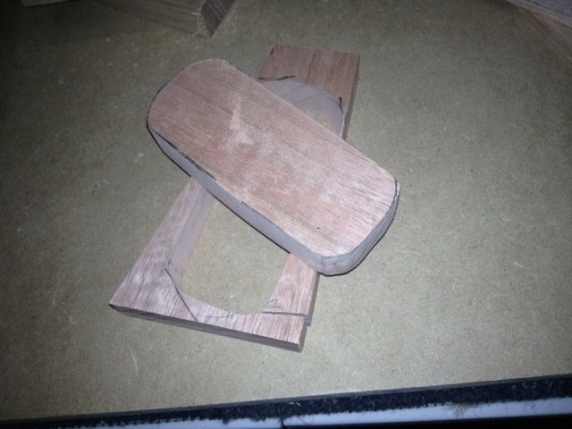
I have used the scroll saw to cut the pickup holder shown below. It is currently too thick for my liking so I will trim it down on the sander.

Hey Gav, can you possibly link me to the PCB Motor Controller and the cream coloured box-thing????Quote from Gavin1393 on January 25, 2013, 12:49
Slightly different design from the previous one I built. But this is the pick-up winder I am building for our good friend Dingobass!
Here is the recipe for this one.
First throw in some Parts....
Sure can!
The cream coloured box-thing is the counter. It's a JDM-11 24 volt resettable counter. Both the counter and the PCB Motor Controller and 800 RPM motor (all 24v) can be obtained from:
http://www.uxcell.com/
They have been pretty good so far!
Cool, also, any wiring diagrams????Quote from Gavin1393 on January 25, 2013, 13:12
Sure can!
The cream coloured box-thing is the counter. It's a JDM-11 24 volt resettable counter. Both the counter and the PCB Motor Controller and 800 RPM motor (all 24v) can be obtained from:
http://www.uxcell.com/
They have been pretty good so far!
And I can't find the controller...

Quote from Gavin1393 on January 25, 2013, 12:57
Building the box and cutting the pickup winder holder to shape. This is the 'empty side' of the winder. Simply seen here, gluing a support for the 'lid' of the winder.
Below is the busy side of the winder after being glued. As you can see I have already drilled the cavity and cut the support which will house the 800 RPM motor. Still to come is the hole for the Reed Switch which will trigger the counter to count the revolutions as well as the 'feeder' that will be used to guide the wire onto the coil.
Note that part of the motor housing is actually loose at the moment. It is not glued to the side and won't be glued. The idea is that this component will be bolted into the glued section so that the motor aan be changed if ever something goes wrong or if the component needs to be shifted or updated.
I have used the scroll saw to cut the pickup holder shown below. It is currently too thick for my liking so I will trim it down on the sander.
I am quivering with anticipation right now!
There is always a workaround for glitches, mistakes and other Guitar building gremlins.....
Ok, spent several hours on this last night!
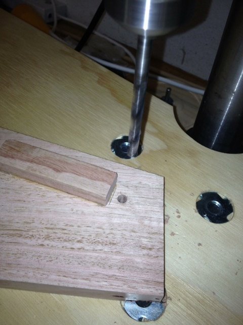
Using the Thicknessing Sander to bring the PUP holder to a more appropriate size and weight.Can'thave the thing flying off the axle and hitting our resident luthier in the face or worse!
Drilling the hole in preparation to attach the wire guide to the 'busy side' of the winder! A bolt with two slides will be inserted here to allow the aforementioned luthier to guide his wiring onto the pickup as it spins completely in control at 600 RPM,10,000 times.
On the subject of the motor, this is the housing with the 'clamps' in place to hold the motor in position. It is adjustable as previously mentioned.
 Posting Permissions

 Reply With Quote
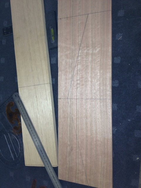
![[url=https://www.facebook.com/kellysgutiars]](image.php?s=7b4a82613d27f58692a38a9188daede0&u=1285&type=sigpic&dateline=1444110346)