Hey guys,
I'm totally new to this, and bought this cheap delay pedal kit off eBay for the soldering practice. I had a pretty good run at soldering all the components to the PCB, but I'm totally flummoxed by this wiring diagram they included.
It's pixelated to buggery, and I don't know enough about wiring to understand what I'm looking at. This is what I THINK is happening, but if someone could correct me I'd really appreciate it...
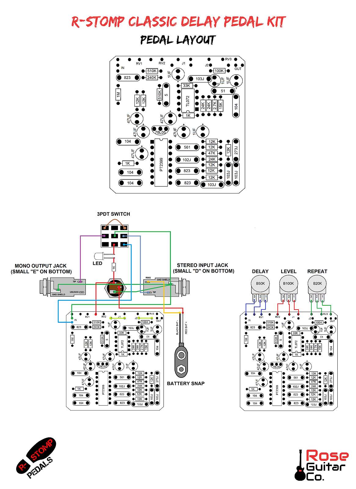
The three lugs on the left hand side of the 3PDT switch are circuit input, guitar input and a jumper
The three lugs on the right are circuit output, guitar output, and the other side of the jumper
The middle three lugs confuse me. There is obviously a connection from the DC jack through the resistor and the LED, and then I'm assuming red lines are power connections, so the red line to the circuit is taking power from the jack (or battery) to the circuit?
Then the battery connections and grounds completely confuse me. I think the black battery connection is going to the top most lug on the input jack (yellow line)? And the red battery connection is going to the DC jack? Then I assume all the green lines are ground wires, and they all connect to the input jack?
Sorry for being so dim. I've spent ages reading forum posts about pedal wiring but I think I got information overload, and it just confused me even more


 Reply With Quote