Page 2 of 2 FirstFirst 1 2
Results 11 to 15 of 15

Thread: Another weird alternative wiring question!

  1. #11
    Overlord of Music WeirdBits's Avatar
    Join Date
    Jan 2013
    Posts
    2,731
    Ok Chuck, as promised, here's a few diagrams… including something that probably fits in the specified 'weird alternative' category.

    The are a couple of caveats with the pickup switching diagrams:
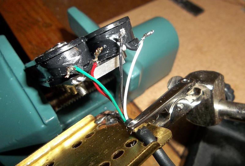
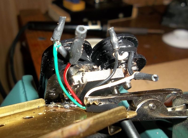
    1. As Simon stated, ideally you need to separate the 'signal' +/- from the shield/ground on the pickup, and P90's typically have a hot core and a braid or bare shield carrying the 'negative' (but it depends on your pickup). The stock PBG P90's usually have a single hot core that connects to the + of the coil and the bare shield is split at the pickup end with one branch connecting to the coil - and the other branch soldered/screwed to the baseplate. In that situation it's actually not that difficult to convert it and connect a two core shielded cable so you've got your required signal separation. The good news is that this only has to be done to the neck pickup, the bridge pup doesn't need to be touched.

    2. Doing parallel, out of phase and series switching using a DP3T switch involves a compromise as it really needs to be a 3 pole 3 throw to get all the connections you need. Basically, for the 'series' mode to function the pickup selector has to be set to the 'neck' position. If it's in the middle or bridge position when in series mode the neck pickup gets shorted out and you only get the bridge regardless.

    This first diagram gives you the requested parallel, parallel out-of-phase, and series options:
    Click image for larger version. 

Name:	Chuck_DP3T_Para_PooP_Series.png 
Views:	237 
Size:	99.3 KB 
ID:	21548

    Diagram two is the 'weird alternative'… I'm calling it the SHoop Gambit. Instead of connecting the pickups in parallel out of phase, why not try Series Half out of Phase… like you can do with humbucker coils to get a pseudo single coil sound. Connecting two P90's in series would be sort-of like a big widely spaced fat humbucker, so I thought using a cap for the half-out-of-phase effect may give you an in-between sound. Some of the fatness of the series connection plus some of the nasally out of phase sound, but without the thinness you get in parallel mode. It's a little out there. I actually wired this up on my 1-string tester yesterday with a couple of P90s (Golden Age bridge and Tonerider neck) and it actually sounded quite nice - different but good and worth exploring. YMMV.
    Click image for larger version. 

Name:	Chuck_DP3T_Para_SHooP_Series.png 
Views:	186 
Size:	166.5 KB 
ID:	21549

    Last diagram is just some tone filtering options. Left is is a single cap version giving both a hi cut and low cut, and the right has separate caps for each filter. Values around 0.0022/0.0033uF will probably give you the most usable sounds, but it's something you need to experiment with for your particular guitar and tastes. From my experience a low cut (cutting out the low end) using a 0.0033 works well, but 0.0022 may be needed to thin it out more. A hi cut with 0.0022 takes off just a bit of the highs, but you may want to go to 0.0033uF or even 0.0047 if you want it a little darker.
    Click image for larger version. 

Name:	Chuck_DP3T_filter_options.png 
Views:	173 
Size:	163.3 KB 
ID:	21550


    (Note: there may have been some alcohol involved, so use at your own risk)
    Scott.

  2. #12
    Mentor Chuck's Avatar
    Join Date
    Aug 2016
    Location
    Sydney
    Posts
    584
    Wow, thanks so much Scott - I so appreciate you doing this! Certainly gets me keen to fire up the soldering iron!!

    Regarding separating the 'signal' +/- from the shield/ground on the pickup that you and Simon have raised, do I just connect one wire from the two-core to the "white" wire in the pic, and the other core is connected to the baseplate as the ground? In the picture you can see that on the PBG P90s I feel like I'm seeing the ground going to both the baseplate and also to the coil...

    Click image for larger version. 

Name:	IMG_2419.JPG 
Views:	149 
Size:	290.6 KB 
ID:	21566
    Completed Builds: #1 TL-1 "Telemaster" (GOTM Oct 2016); #2 The "Maplecaster" scratch build; #3 JB-4 "Bass IV" (co-winner GOTM Jan 2017); #4 ST-1M "Surfcaster" (GOTM Apr 2017), #5 JZA-1 "EC Deluxe"

    In Progress:
    Build #6 N1R "Semi-scratch" build
    Build #7 JZA-1 Baritone

    The Cavan Project
    The Magnificent Compañeros

  3. #13
    GAStronomist Simon Barden's Avatar
    Join Date
    Oct 2016
    Location
    Reading, UK
    Posts
    10,547
    The shield wire in the picture is going to both the base plate and one end of the coil. You'd need a 2-core plus shield cable, One of the cores will go to the same end of the coil as the white cable, the other core would go to the other end of the coil which the shield is currently connected to. You are going to have to unwrap the tape around the coils to get to the joins. The shield then connects just to the baseplate.

  4. #14
    Mentor Chuck's Avatar
    Join Date
    Aug 2016
    Location
    Sydney
    Posts
    584
    Quote Originally Posted by Simon Barden View Post
    The shield wire in the picture is going to both the base plate and one end of the coil. You'd need a 2-core plus shield cable, One of the cores will go to the same end of the coil as the white cable, the other core would go to the other end of the coil which the shield is currently connected to. You are going to have to unwrap the tape around the coils to get to the joins. The shield then connects just to the baseplate.
    Cool - thanks Simon, sounds both complicated and simple at the same time! I'll see if I can muddle through!
    Completed Builds: #1 TL-1 "Telemaster" (GOTM Oct 2016); #2 The "Maplecaster" scratch build; #3 JB-4 "Bass IV" (co-winner GOTM Jan 2017); #4 ST-1M "Surfcaster" (GOTM Apr 2017), #5 JZA-1 "EC Deluxe"

    In Progress:
    Build #6 N1R "Semi-scratch" build
    Build #7 JZA-1 Baritone

    The Cavan Project
    The Magnificent Compañeros

  5. #15
    Overlord of Music WeirdBits's Avatar
    Join Date
    Jan 2013
    Posts
    2,731
    The coil wires on these pickups are incredibly fragile and it's very easy to break them and/or the attachment points of the actual shielded cable. I'd actually suggest just snipping the existing single core shielded cable through the yellow casing ~5-10mm short of where it's stripped, then carefully separate the 3 parts (core, bare to coil, and bare to baseplate). Make sure you'll be able to insulate the bare to coil wire with heatshrink and, if you can, then attach some new 2-core shield wire. One core to each of the snipped coil wires and the shield to the baseplate.

    I did this type of procedure on a PBG humbucker, snipping and attaching new cable, and it worked well. If you look carefully in this image you can see my new green wire is connecting to what was the original bare wire coil connection. I slipped some heatshrink over the original bare wire so it couldn't short with anything once it was all buttoned up.


    Topped off with more heatshrink before adding some more tape around the coils and sealing it up.
    Last edited by WeirdBits; 13-08-2017 at 12:43 PM.
    Scott.

Page 2 of 2 FirstFirst 1 2

Posting Permissions

  • You may not post new threads
  • You may not post replies
  • You may not post attachments
  • You may not edit your posts
  •